System and method for representing a general two dimensional spatial transformation

Active Publication Date: 2006-03-09
GEO SEMICONDUCTOR INC
View PDF27 Cites 52 Cited by
  • Summary
  • Abstract
  • Description
  • Claims
  • Application Information

AI Technical Summary

Problems solved by technology

This objective often leads to restrictions on the complexity of the spatial transformation or unrealistic descriptions of the transformation.
However, the two-pass method is prone to the bottleneck effect, i.e. large compression in intermediate image, leading to loss of data.
In the extreme case, complete data loss can occur, e.g. where an area is compressed to a line.
Other problems with the two-pass method involve generating the intermediate pass data.
A pixel-by-pixel description requires large storage spaces and more importantly, does not allow simple means for additional data manipulations.
In a pixel-by-pixel description, the entire grid has to be re-generated for a zooming warp, which can be inefficien

Method used


Image

  • System and method for representing a general two dimensional spatial transformation
  • System and method for representing a general two dimensional spatial transformation
  • System and method for representing a general two dimensional spatial transformation

Examples


Embodiment Construction

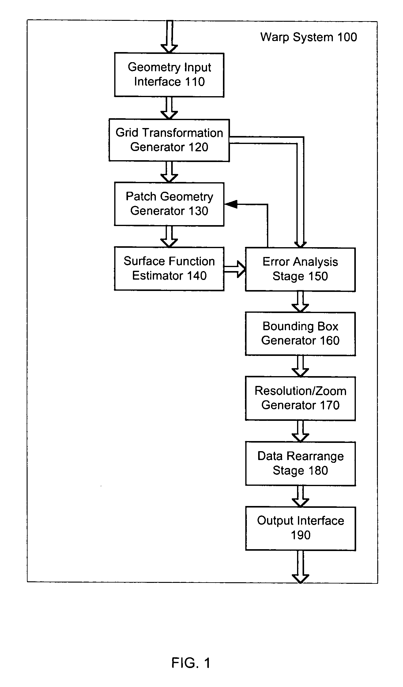
[0027] Reference is first made to FIG. 1 which shows an example of a warp system 100 made in accordance with a preferred embodiment of the present invention. Warp system 100 includes a geometry input interface 110, a grid transformation generator 120, a patch geometry generator 130, a surface function estimator 140, an error analysis stage 150, a bounding box generator 160, a resolution / zoom generator 170, a data rearrange stage 180, and an output interface 190.

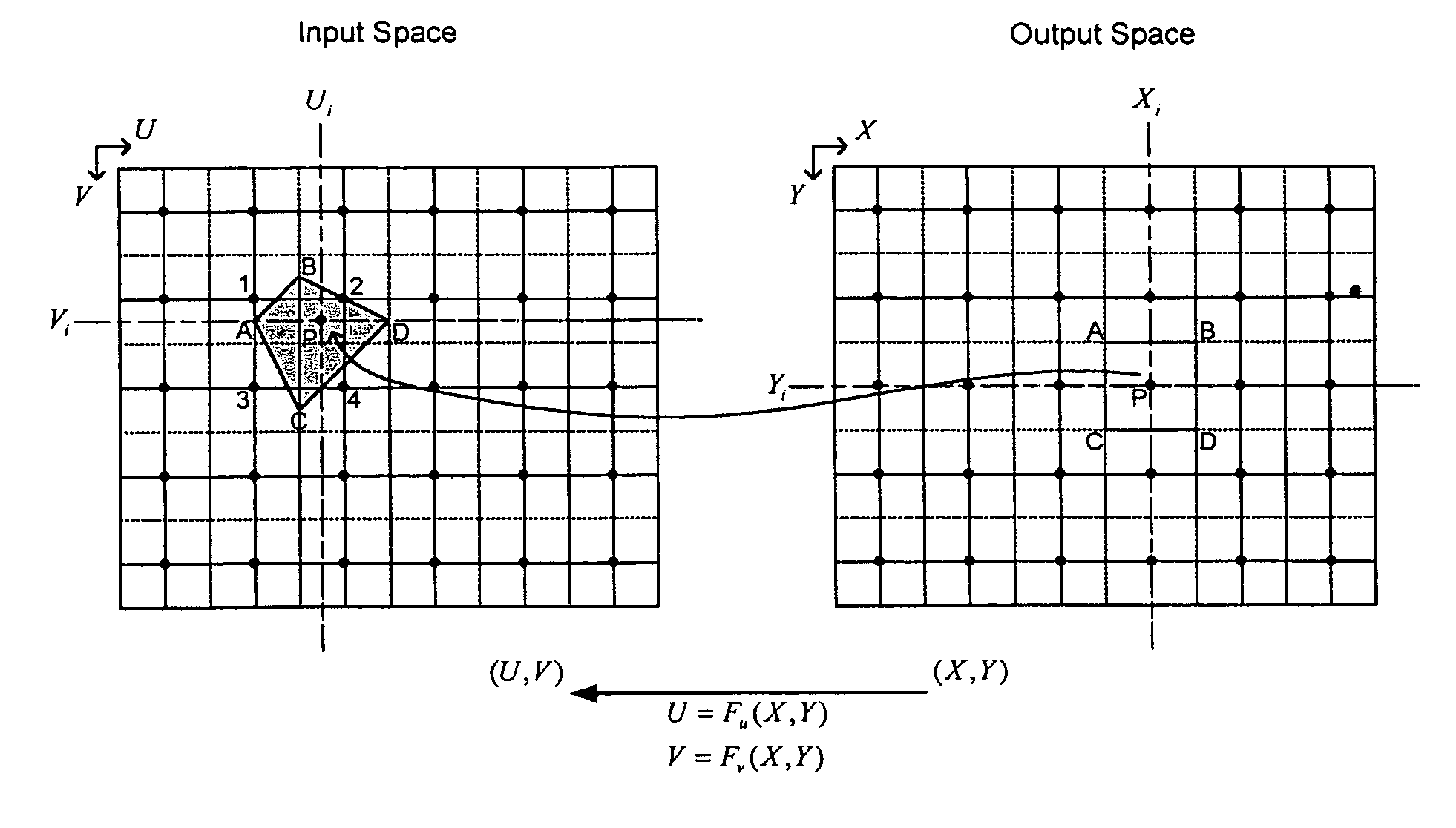
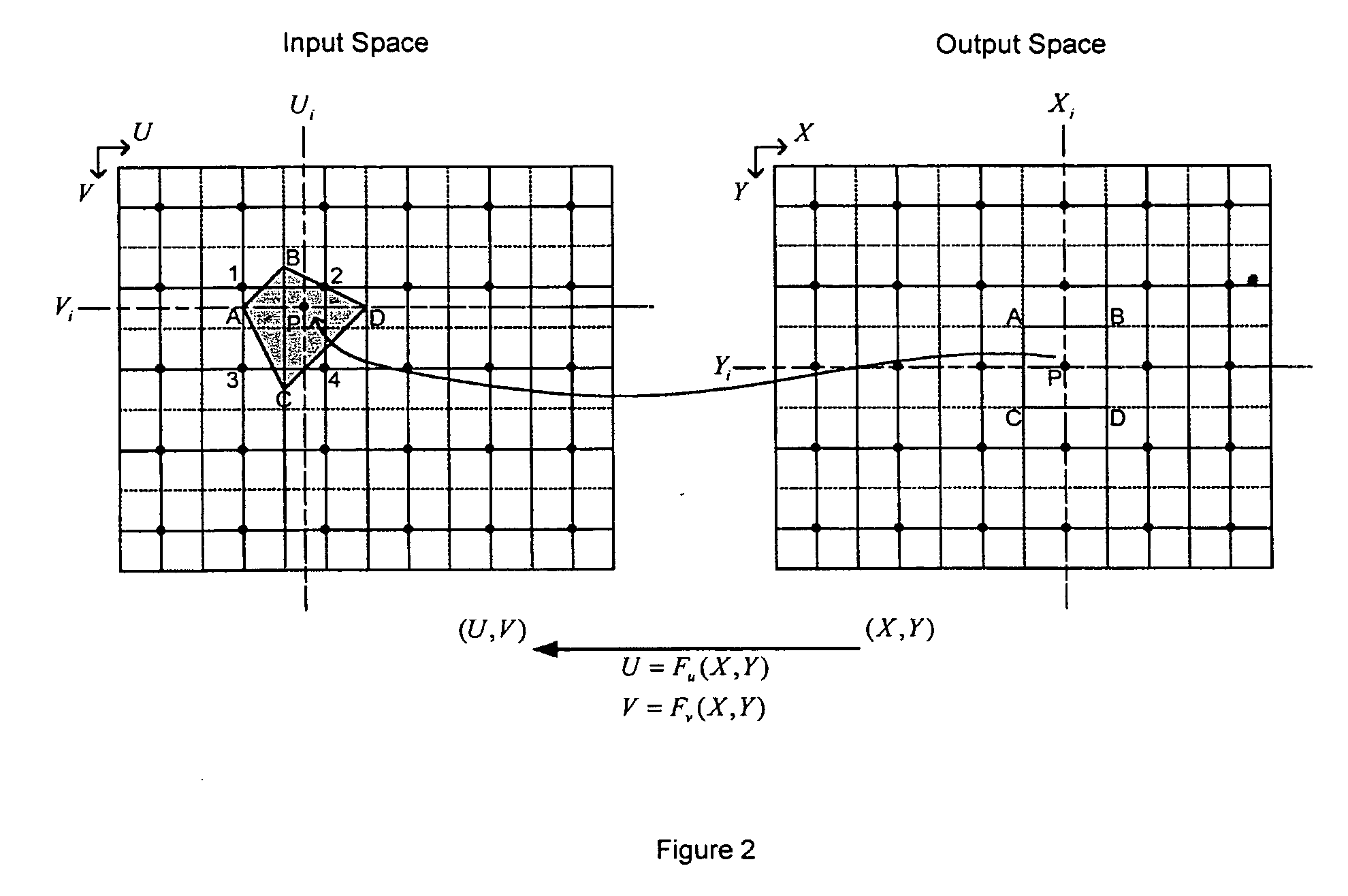
[0028] Warp system 100 transforms a grid data (pixel-by-pixel) representation to a surface functional representation, which results in an efficient real-time hardware implementation. Any system where a 2D spatial transformation needs to be applied can make use of warp system 100. Warp system 100 can be used in applications ranging from correcting small distortions in projectors, cameras, and display devices, to correcting for perspectives like keystone or special wide-angle lens corrections, and to a complete change in image...


PUM


Abstract

A system and method for representing a two-dimensional spatial transformation that describes the transformation by an inverse mapped grid data set. The grid data for each coordinate is surface fitted on an array of rectangular patches defined in the output space using numerical techniques. Error analysis determines whether a finer mesh resolution is required for surface fitting. The spatial transformation is then defined by the array of rectangular surface patches and the set of surface coefficients such that the spatial transformation can be executed through evaluation of the surface polynomials. The two-dimensional surface polynomial representation allows the transformation to be easily adjusted for scale changes and zooming and panning effects.

Description

FIELD OF THE INVENTION [0001] This invention relates to digital image data transformations, and more particularly to the representation of two-dimensional spatial transformation of digital image data. BACKGROUND OF THE INVENTION [0002] Most image processing systems can be considered in part as a spatial transformation system. In two-dimensional (2D) image processing, an image is generated by assigning a “color” value to every pixel in the 2D output space according to that pixel's relationship to some input data (possibly 3D). Introducing a coordinate system on the input and output data spaces, this relationship is conveniently expressed as a spatial mapping. The spatial mapping may be implicit in the design of the image processing system (lens arrangement, etc.), or may be explicitly specified to obtain a certain effect. Image warping, a term referring to a mapping between 2D input and output images or spaces, is often applied to correct optical distortions and various artifacts, su...

Claims


Application Information

Patent Timeline
IPC IPC(8): G06T15/20
CPCG06T3/0006
Inventor BASSI, ZORAWAR S.
Owner GEO SEMICONDUCTOR INC
Why Eureka
Try Eureka