Diaphragm

a diaphragm and diaphragm technology, applied in the field of diaphragms, can solve the problems of increasing manufacturing costs, deteriorating the property of the diaphragm, and inability to reduce the thickness of the diaphragm satisfactorily, so as to achieve the effect of further reducing the appearance of ghosts and flares

Inactive Publication Date: 2006-03-09
FUJI PHOTO OPTICAL CO LTD
View PDF7 Cites 19 Cited by
  • Summary
  • Abstract
  • Description
  • Claims
  • Application Information

AI Technical Summary

Benefits of technology

[0015] Since the inner circumferential surface of the thin plate in which the aperture is formed is subjected to a surface treatment for suppressing the light reflection thereon, the reflection of the light on the inner circumferential surface of aperture can be held down. This makes it possible to provide a diaphragm in which the occurrence of a ghost and a flare are further reduced.

Problems solved by technology

In the diaphragm made of one piece of the above-mentioned plastic sheet, the thickness thereof cannot be reduced satisfactorily since the diaphragm has the problems of the strength and light shielding property thereof.
Even when a sheet of around 0.2 to 0.3 mm in thickness is used, a ghost / a flare occurring due to the reflected light from the edge portion of the diaphragm necessarily causes the deterioration of the property of the diaphragm.
However, the diaphragm disclosed in JPA '138 needs to prepare two pieces of sheets formed by the press working respectively, and an operation for pasting the sheets on each other accurately with a bonding agent so that the centers of the diaphragm aperture are aligned with each other becomes necessary, so that the manufacturing cost increases.
Since the thin sheet provided with the diaphragm aperture is as thin as 0.04 to 0.09 mm, the surrounding portion of the aperture, which is not laminated on the thick sheet, of the thin sheet has light transmission of around 5%, i.e., the light shielding property was unsatisfactory.

Method used


Image

  • Diaphragm
  • Diaphragm
  • Diaphragm

Examples


Embodiment Construction

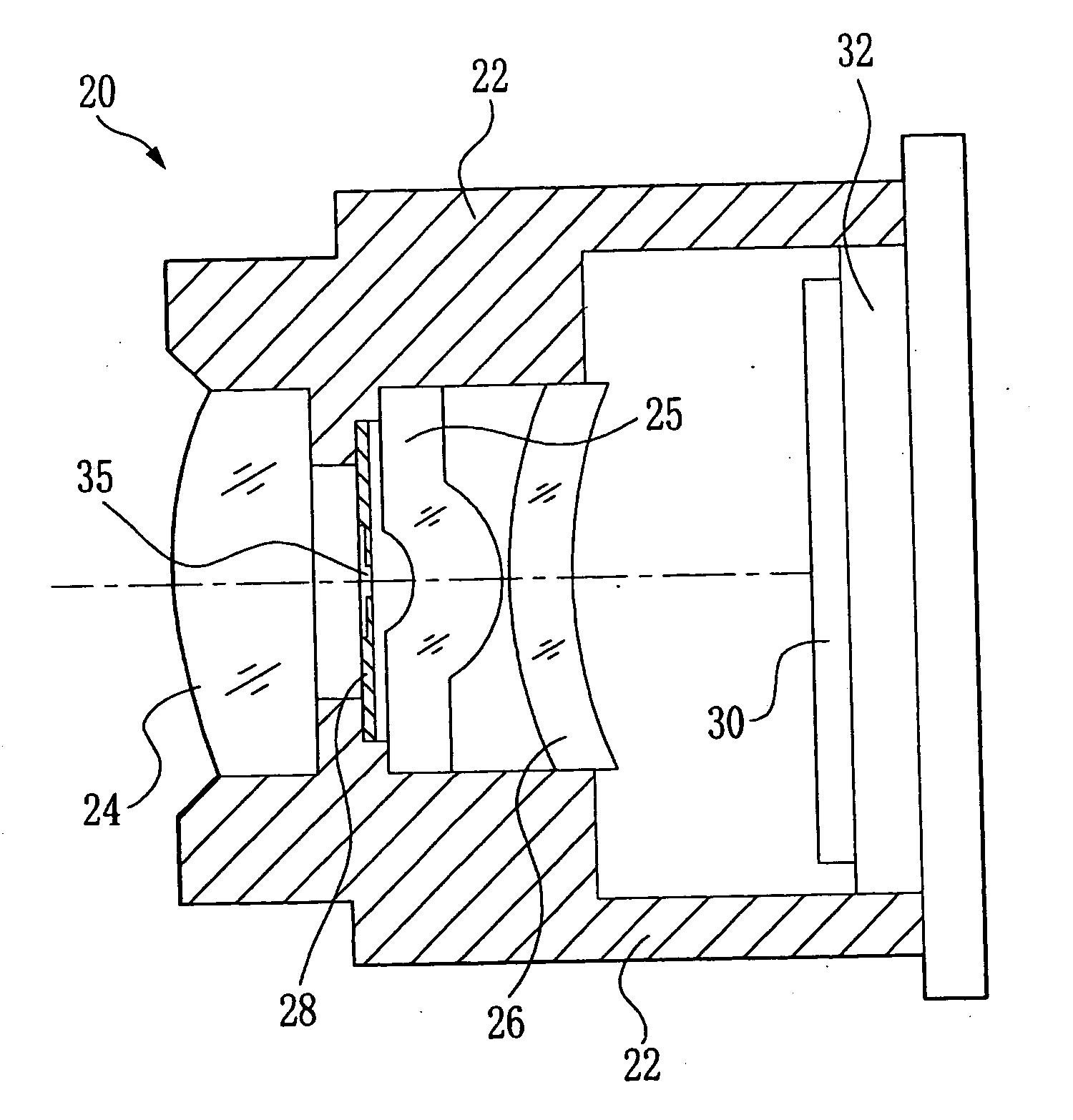
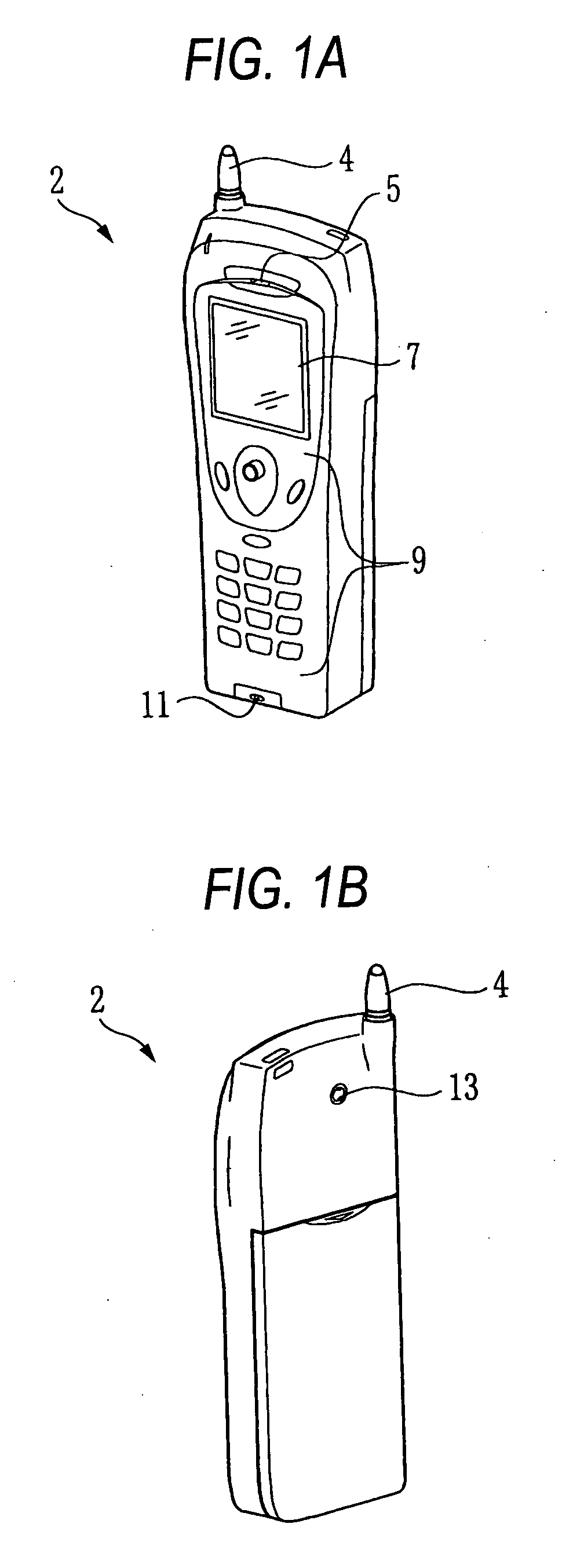
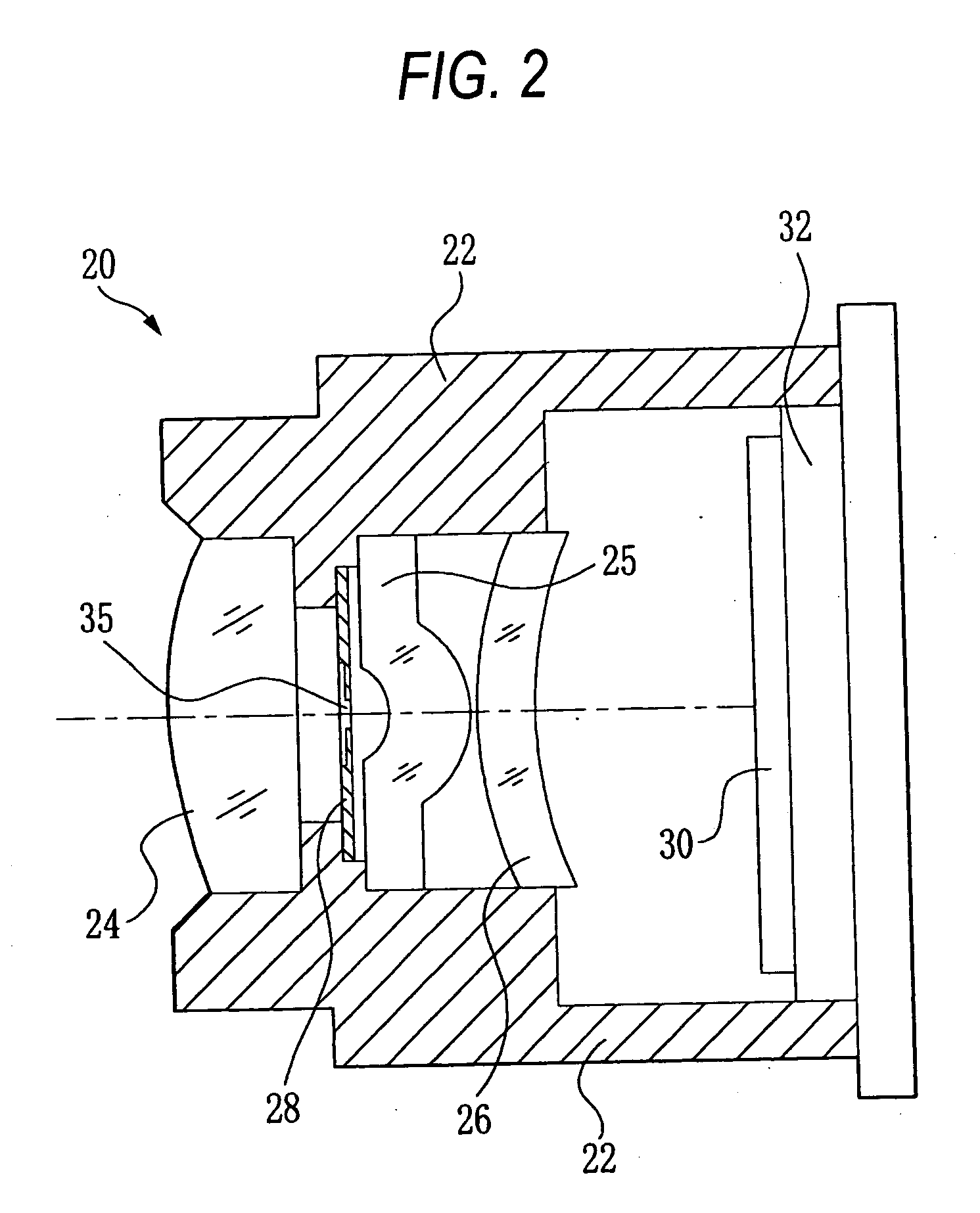
[0041]FIG. 1 shows a camera-carrying portable telephone containing the diaphragm according to one embodiment of the present invention therein. As shown in FIG. 1A, the camera-carrying portable telephone 2 is provided at an upper portion thereof with a communication antenna 4, and at an upper portion of a front surface thereof with a receiving speaker 5 for outputting the voice of the opposite speaking party, an image displaying liquid crystal frame 7, an operating buttons 9 for carrying out various operations including the inputting of a telephone number and the like, a transmission microphone 11 for transmitting the voice of a user to the opposite speaking party, and the like. FIG. 1B is a perspective view showing a rear surface of the camera-carrying portable telephone. A first lens 24 provided in a lens unit, which will be described later, is exposed to the outside of the rear surface of the camera-carrying portable telephone 2. The camera-carrying portable telephone 2 can switch...


PUM


Abstract

A diaphragm comprising a single plate, the single plate comprising: a first plate portion having an aperture; and a second plate portion formed at an outer side of the first plate portion, wherein a first thickness of the first plate portion is thinner than a second thickness of the second plate portion.

Description

[0001] This application is based on Japanese Patent application JP 2004-257683, filed Sep. 3, 2004, the entire content of which is hereby incorporated by reference. This claim for priority benefit is being filed concurrently with the filing of this application. BACKGROUND OF THE INVENTION [0002] 1. Technical Field of the Invention [0003] The present invention relates to a diaphragm inserted with an optical system, such as an imaging lens into a lens barrel and put to use. [0004] 2. Description of the Related Art [0005] A diaphragm is incorporated in a lens unit of a camera and the like. A variable diaphragm unit a diameter of an aperture of which can be regulated in accordance with the brightness and the like is often used as a diaphragm incorporated in a lens unit. The lens units incorporated in, for example, a simplified photographic camera like a lens-carrying film unit, and the lens units of a simplified digital camera incorporated in a portable telephone also include a lens uni...

Claims


Application Information

Patent Timeline
Patent Type & Authority Applications(United States)
IPC IPC(8): G03B9/02
CPCG03B29/00G03B9/04
Inventor OKUMURA, TETSUYA
Owner FUJI PHOTO OPTICAL CO LTD
Why Eureka
Try Eureka