Removal of carbon dioxide from air

Inactive Publication Date: 2006-03-09
THE TRUSTEES OF COLUMBIA UNIV IN THE CITY OF NEW YORK +2
View PDF99 Cites 250 Cited by
  • Summary
  • Abstract
  • Description
  • Claims
  • Application Information

AI Technical Summary

Benefits of technology

[0020] The advantages of this invention are several: First, the process greatly streamlines the overall flow sheet of carbon dioxide capture from air, by avoiding the intermediate step of transferring the carbonate ion to calcium carbonate which is then calcined to free the CO2. The mass handling of such a transfer

Problems solved by technology

However, as greenhouse gas concerns mount, CO2 emissions from all sources will have to be curtailed.
Although these methods are efficient in removing CO2, they have a serious disadvantage in that for them to efficiently remove carbon dioxide from the air, the air must be driven by the sorbent at a fairly high pressure, because relatively high pressure losses occur during the washing process.
Furthermore, in order to obtain the increased pressure, compressing means of some nature are required and these means use up a certain amount of energy.
This additional energy used in compressing the air can have a particularly unfavorable effect with regard to the overall carbon dioxide balance of the process, as the energy required for increasing the air pressure would produce its ow

Method used


Image

  • Removal of carbon dioxide from air
  • Removal of carbon dioxide from air
  • Removal of carbon dioxide from air

Examples


Embodiment Construction

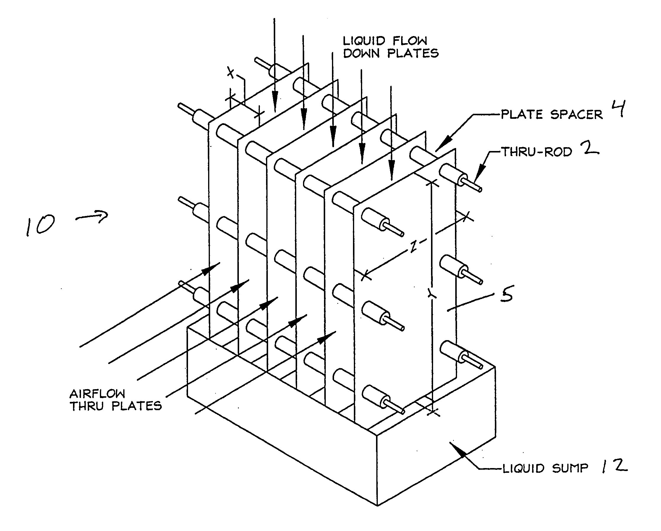
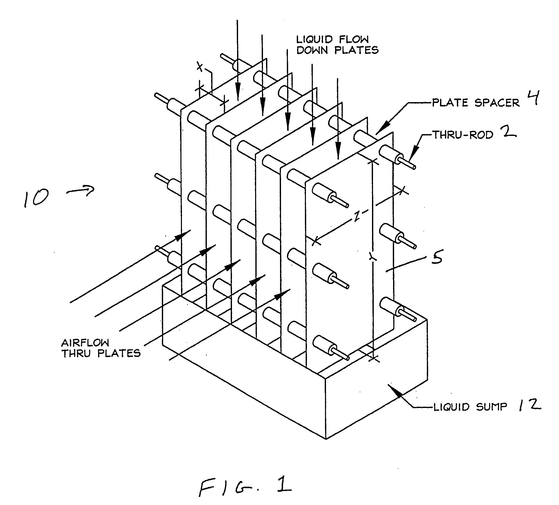
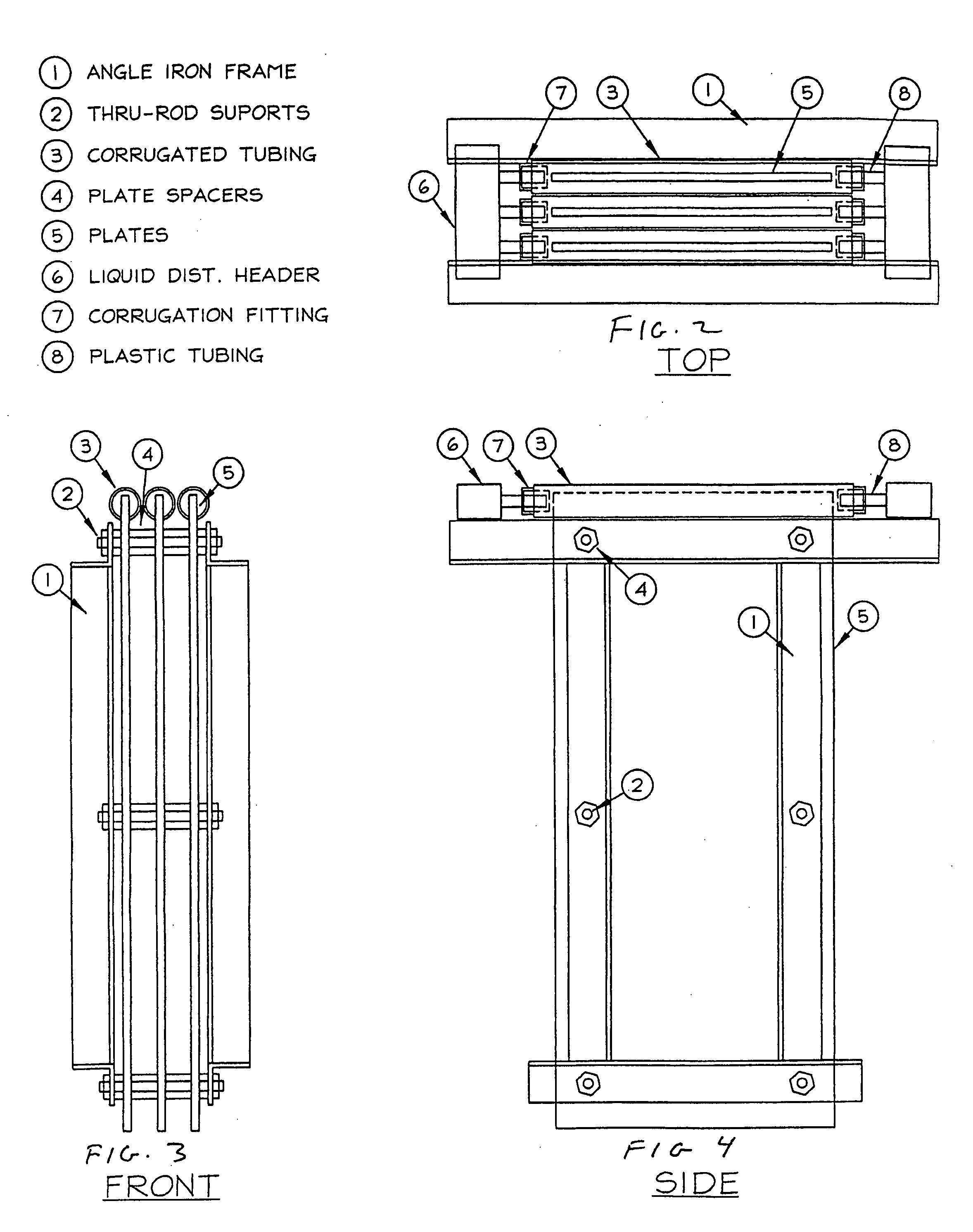
[0029] Referring first to FIGS. 1-4, an air scrubber unit according to one aspect of the present invention removes CO2 from an airflow that is maintained by a low-pressure gradient. The air scrubber units consist of a wind collector 10 having lamella, which are two sheets or plates 5 covered in downward flowing sorbent bounding a thin air space, and a liquid sump 12. The two sheets forming the lamella preferably are separated by spacers 4 laced between the sheets on thru-rods 2 supported by a rigid frame 1 although the lamella may be supported in spaced relation by other means.

[0030] In general, the sorbent material flows down the lamella sheets, while the airflow passes between the thin airspace between the sheets. The contact between the air and the sorbent material causes a chemical reaction that removes CO2. However, the air scrubber units could also capture other gases present in the air.

[0031] Sorbent is applied to the lamella sheets according to established state of the art...


PUM


Abstract

The present invention is directed to methods for removing carbon dioxide from air, which comprises exposing solvent covered surfaces to air streams where the airflow is kept laminar, or close to the laminar regime. The invention also provides for an apparatus, which is a laminar scrubber, comprising solvent covered surfaces situated such that they can be exposed to air stream. In another aspect, the invention provides a method and apparatus for separating carbon dioxide (CO2) bound in a solvent. The invention is particularly useful in processing hydroxide solvents containing CO2 captured from air.

Description

CROSS REFERENCE TO RELATED APPLICATIONS [0001] This application claims priority from U.S. Provisional Application Ser. No. ______ filed Aug. 20, 2004, and from U.S. Provisional Application Ser. No. 60 / 603,811 filed Aug. 23, 2004, and from U.S. Provisional Application Ser. No. 60 / 611,493, filed Sep. 20, 2004, the contents of which are incorporated herein by reference.BACKGROUND OF THE INVENTION [0002] The present invention in one aspect relates to removal of selected gases from air. The invention has particular utility for the extraction of carbon dioxide (CO2) from air and will be described in connection with such utilities, although other utilities are contemplated. [0003] Extracting carbon dioxide (CO2) from ambient air would make it possible to use carbon-based fuels and deal with the associated greenhouse gas emissions after the fact. Since CO2 is neither poisonous nor harmful in parts per million quantities but creates environmental problems simply by accumulating in the atmosp...

Claims


Application Information

Patent Timeline
IPC IPC(8): B01D53/62
CPCB01D53/1475B01D53/62Y02C10/06B01D61/445Y02C10/04B01D53/965Y02A50/20Y02C20/40
Inventor WRIGHT, ALLEN B.LACKNER, KLAUS S.
Owner THE TRUSTEES OF COLUMBIA UNIV IN THE CITY OF NEW YORK
Why Eureka
Try Eureka