
Medical cockpit system

a cockpit system and medical technology, applied in the field of medical cockpit systems, can solve the problem of insufficient transmission of information

Inactive Publication Date: 2006-03-09
KYOTO UNIV
View PDF2 Cites 147 Cited by
  • Summary
  • Abstract
  • Description
  • Claims
  • Application Information

AI Technical Summary

Benefits of technology

The present invention provides a medical cockpit system that connects a clinic and a medical cockpit through a network. The system includes a clinic camera, a clinic voice information obtaining means, a physical information camera, and a monitor for displaying video from the clinic camera and the physical information camera. The system also includes a database for accumulating patient data and sending it to the medical cockpit. The medical cockpit system includes a first monitor for obtaining measurement information and video from the clinic, a second monitor for displaying the video from the clinic camera, and a third monitor for displaying the physical information camera. The second monitor can switch between the video from the clinic camera and the physical information camera. The system allows the operator to concentrate on the patient and the medical procedure while remotely controlling it. The system can also be used for educational or training purposes.

Problems solved by technology

According to this apparatus, the images of the affected part and its periphery and the contact force information of the tip end of the working machine to the affected part are transmitted to the doctor, but information in the operation room required by the doctor is not always transmitted, and sufficient information is not transmitted in various remote surgical operations in some cases.

Method used


Image

  • Medical cockpit system
  • Medical cockpit system
  • Medical cockpit system

Examples


Embodiment Construction

[0062] An embodiment of the present invention will be explained based on the drawings below.

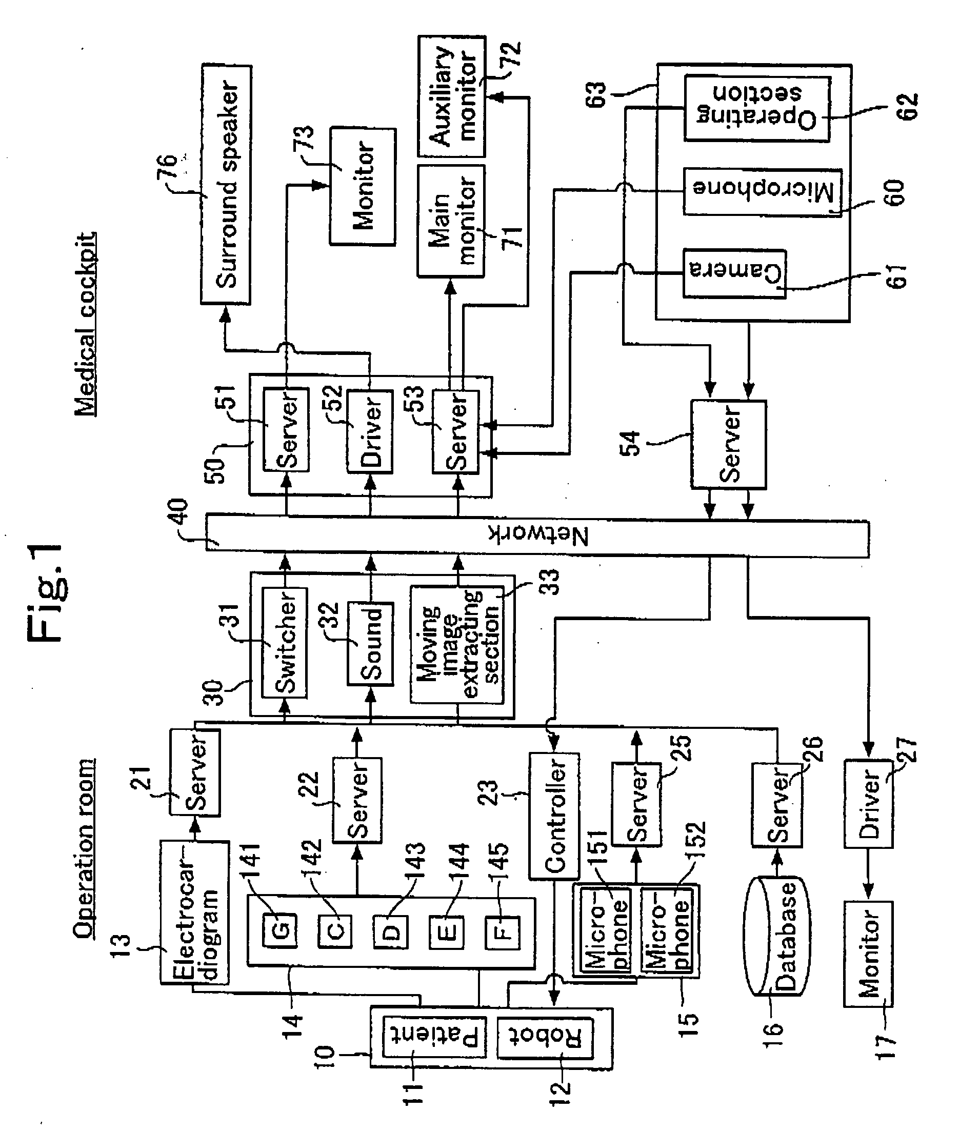
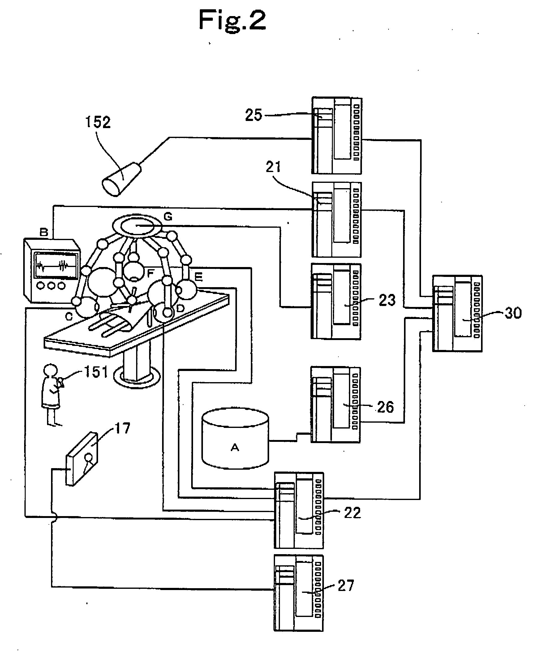
[0063]FIG. 1 is a block diagram showing the entire structure of a medical cockpit system of an embodiment. In an operation room, a patient 11 is lying on an operating table 10. An operation manipulator or a robot (robot, hereinafter) 12 is disposed as an operation tool near the operating table 10. The robot 12 carries out surgical operation motion in accordance with instructions of the controller 23.

[0064] In an operation room, a measurement information obtaining apparatus 13 such as electrocardiogram for measuring electrocardiogram information for obtaining an electrocardiogram of a patient is disposed. The information is accumulated in a measurement information server 21. In the operation room, there are a camera apparatus (operation room camera means) 141 for shooting a state of the operation room and camera apparatuses (body information camera means) 142, 143, 144 and 145 for shooting a...


PUM


Abstract

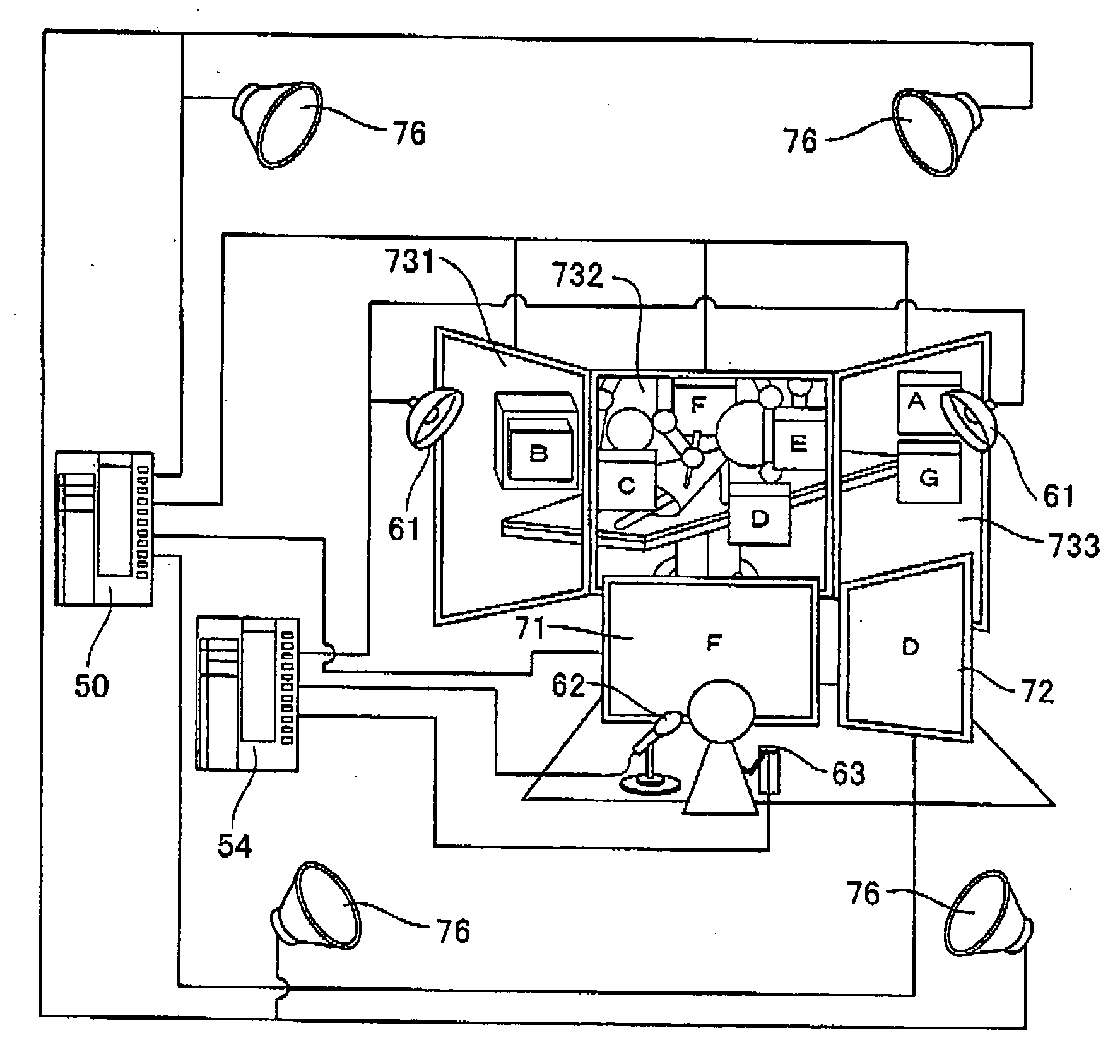
Measurement information of a patient 11 in a clinic, video of a medical procedure site, voice in the clinic, and video information of a body including an affected part of the patient are integrated and sent to a medical cockpit through a network 40. In the medical cockpit, the video of the clinic is outputted on a large screen monitor 73, and the sent measurement information and a plurality of sets of body video information are switched and inset in predetermined positions in the monitor 73 and reproduced. An enlarged moving image of the affected part is reproduced on a main monitor 71. Measurement information of the patient 11, moving image information such as video information of the body including the affected part of the patient or enlarged image information is reproduced on an auxiliary monitor 72. The voice information of the clinic is reproduced by a surround speaker 76. A doctor operates a medical procedure section 62 and controls a knife operating section 121 of a robot 12 in the clinic while seeing the images on the main monitor and the auxiliary monitor.

Description

TECHNICAL FIELD [0001] The present invention relates to a medical cockpit system for carrying out medical procedure such as examination, inspection, diagnosis, treatment and other proceeding by remote control, and relates to a medical cockpit used for the medical cockpit system. BACKGROUND TECHNIQUE [0002] In recent years, as information network technique is progressing, remote surgical operation in which a plurality of medical locations are connected to each other and surgical operation of a patient who is at a remote location is carried out by remote control is in the limelight. Japanese Patent Application Laid-open No. H7-184923 discloses an apparatus which carried out such remote surgical operation. According to a method described in this publication, surgical operation is carried out by remote control in a narrow space. The apparatus includes operation environment information detecting means which detects images of an affected part and its periphery and a contact force of a tip...

Claims


Application Information

Patent Timeline
Patent Type & Authority Applications(United States)
IPC IPC(8): A61B5/05A61B90/00A61B5/00A61B34/35
CPCA61B19/2203A61B19/52A61B19/5212A61B5/0013G06F19/3406G06F19/3418A61B2017/00203A61B90/36A61B90/361A61B34/30G16H40/63G16H40/67G16H30/20
Inventor TAKAHASHI, TAKASHIOYAMA, HIROSHIKURODA, TOMOHIROHORI, KENTA
Owner KYOTO UNIV
Learn More