Use of generated SQL for evaluation of decision point rules in a workflow system

Inactive Publication Date: 2006-03-09
IBM CORP
View PDF19 Cites 29 Cited by
  • Summary
  • Abstract
  • Description
  • Claims
  • Application Information

AI Technical Summary

Problems solved by technology

In addition, because the decision point work node is implemented in the server and because the server determines whether to route a work package to a client work node, the client work nodes do not determine whether they should process the work package.

Method used


Image

  • Use of generated SQL for evaluation of decision point rules in a workflow system
  • Use of generated SQL for evaluation of decision point rules in a workflow system
  • Use of generated SQL for evaluation of decision point rules in a workflow system

Examples


Embodiment Construction

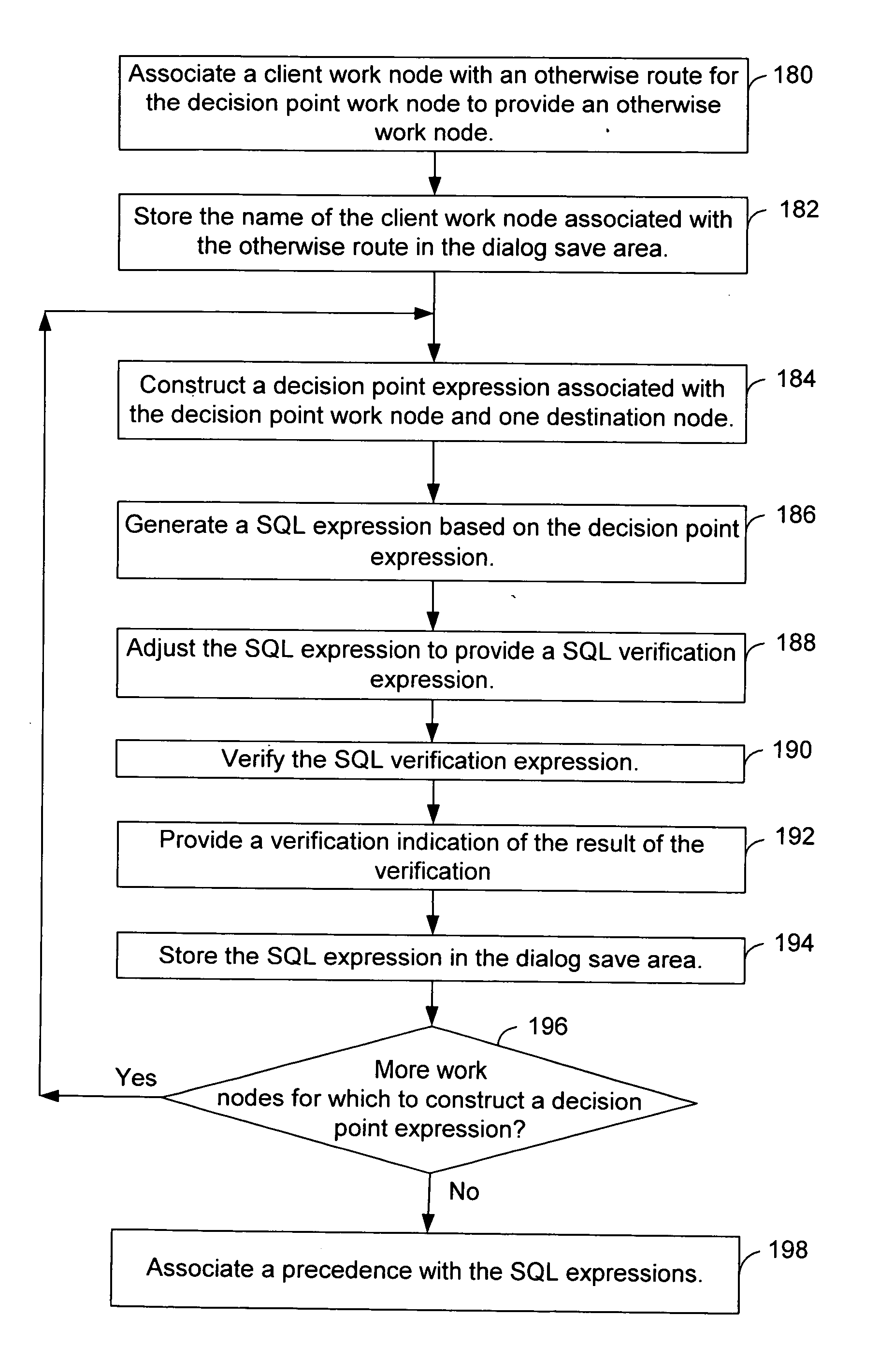
[0039] After considering the following description, those skilled in the art will clearly realize that the teachings of the various embodiments of the present invention can be utilized to provide a decision point in a workflow system. In various embodiments, a workflow system comprises a server and at least a first client work node. A decision point work node is provided at the server. A SQL expression which is associated with the decision point work node and the first client work node is generated. The server determines whether to route a work package to the first client work node based on the SQL expression.

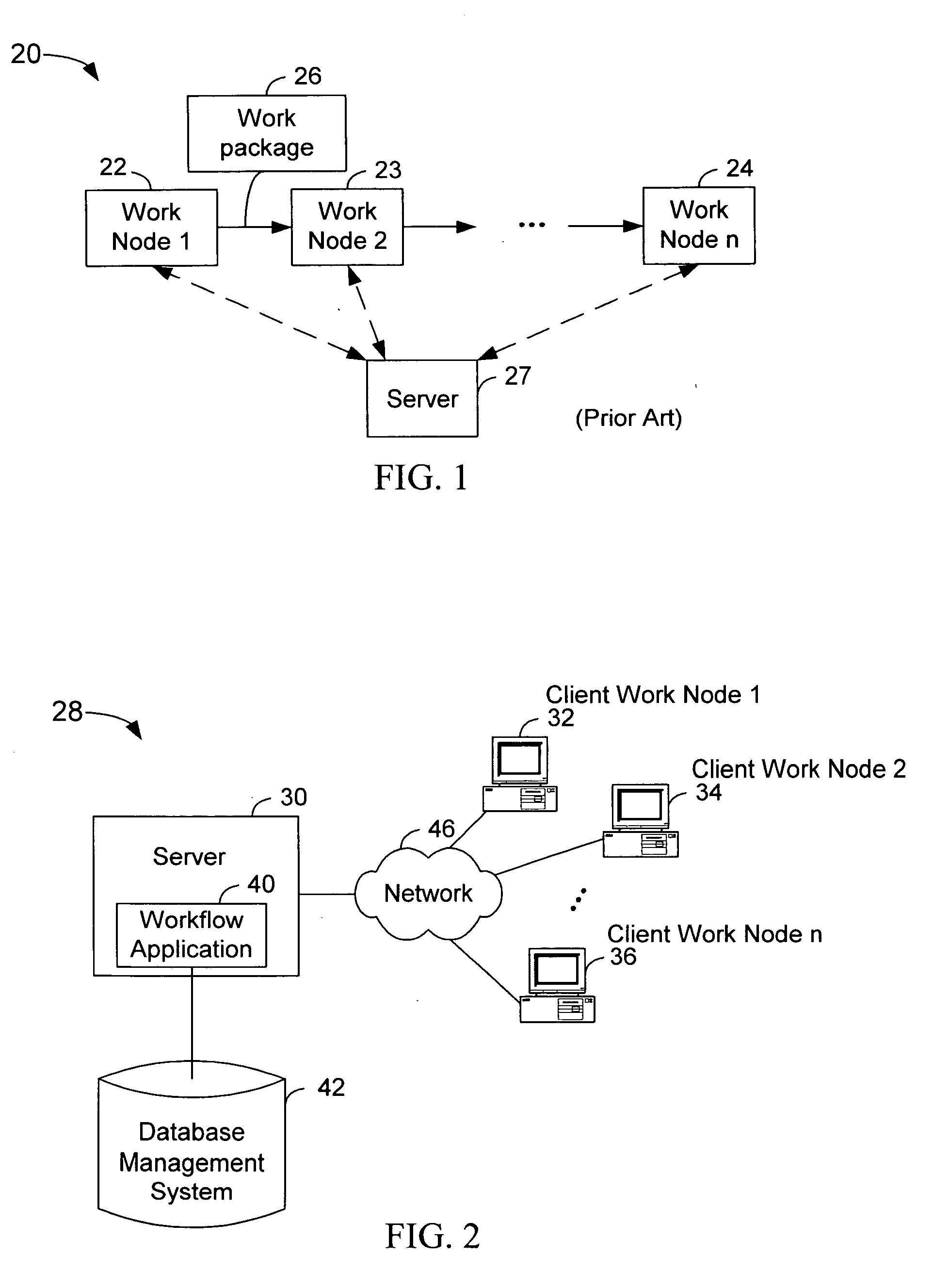
[0040]FIG. 2 depicts a high-level block diagram of an exemplary workflow system 28 which uses various embodiments of the present invention. In the workflow system 28, the server 30 is coupled to client work nodes 32-36. The server 30 executes a workflow application 40 that uses various embodiments of the present invention. The workflow application 40 is coupled to a database m...


PUM


Abstract

Various embodiments of a method, apparatus and article of manufacture provide a decision point in a workflow system comprising a server and at least a first client work node. A decision point work node is provided at the server. A SQL expression which is associated with the decision point work node and the first client work node is generated. The server determines whether to route a work package to the first client work node based on the SQL expression.

Description

BACKGROUND OF THE INVENTION [0001] 1. Field of the Invention [0002] This invention relates to a workflow system; and in particular, this invention relates to using a generated structured query language (SQL) expression for evaluation of decision point rules in a workflow system. [0003] 2. Description of the Related Art [0004] Workflow systems are used to process documents. In a workflow system, documents are distributed to users at work nodes. [0005]FIG. 1 depicts a block diagram of a conventional workflow process 20 having n work nodes 22-24. At work node 122, a user scans a document, for example, an insurance claim for an insured person. Work node 122 produces a work package 26 containing the scanned document. Work node 122 sends the work package 26 to another work node 23 for further processing. For example, at work node 23, another user may verify that the information in the document is completed for certain fields. At work node 23, the work package 26 is processed and forwarded...

Claims


Application Information

Patent Timeline
Patent Type & Authority Applications(United States)
IPC IPC(8): G06F17/30
CPCG06Q10/06G06F17/30421G06F16/2448
Inventor BHAGHAVAN, RUPAMILLER, WAYNE FREDERICKNELSON, KENNETH CARLINSANDERS, SHARON MCKENNAWANG, FANG-YI
Owner IBM CORP
Why Eureka
Try Eureka