
Apparatus with redundant circuitry and method therefor

a technology of circuitry and apparatus, applied in the direction of electric digital data processing, instruments, digital data processing details, etc., can solve the problems of increasing system layout complexity and chip susceptibility, increasing cost, and difficult effective redundancy

Active Publication Date: 2006-03-09
ATI TECH INC
View PDF11 Cites 47 Cited by
  • Summary
  • Abstract
  • Description
  • Claims
  • Application Information

AI Technical Summary

Problems solved by technology

However, with large parallel floating point resources that are used in graphics processors, or other processing devices, or any other suitable Arithmetic Logic Units, effectively employing redundancy can be quite difficult since the silicon area may be quite large and the inner connections quite complex.
However, routing all inputs to a redundant circuit may require too much wiring that may increase system layout complexity and chip susceptibility to increased noise and thus potentially reduce yields and increase cost.

Method used


Image

  • Apparatus with redundant circuitry and method therefor
  • Apparatus with redundant circuitry and method therefor
  • Apparatus with redundant circuitry and method therefor

Examples


Embodiment Construction

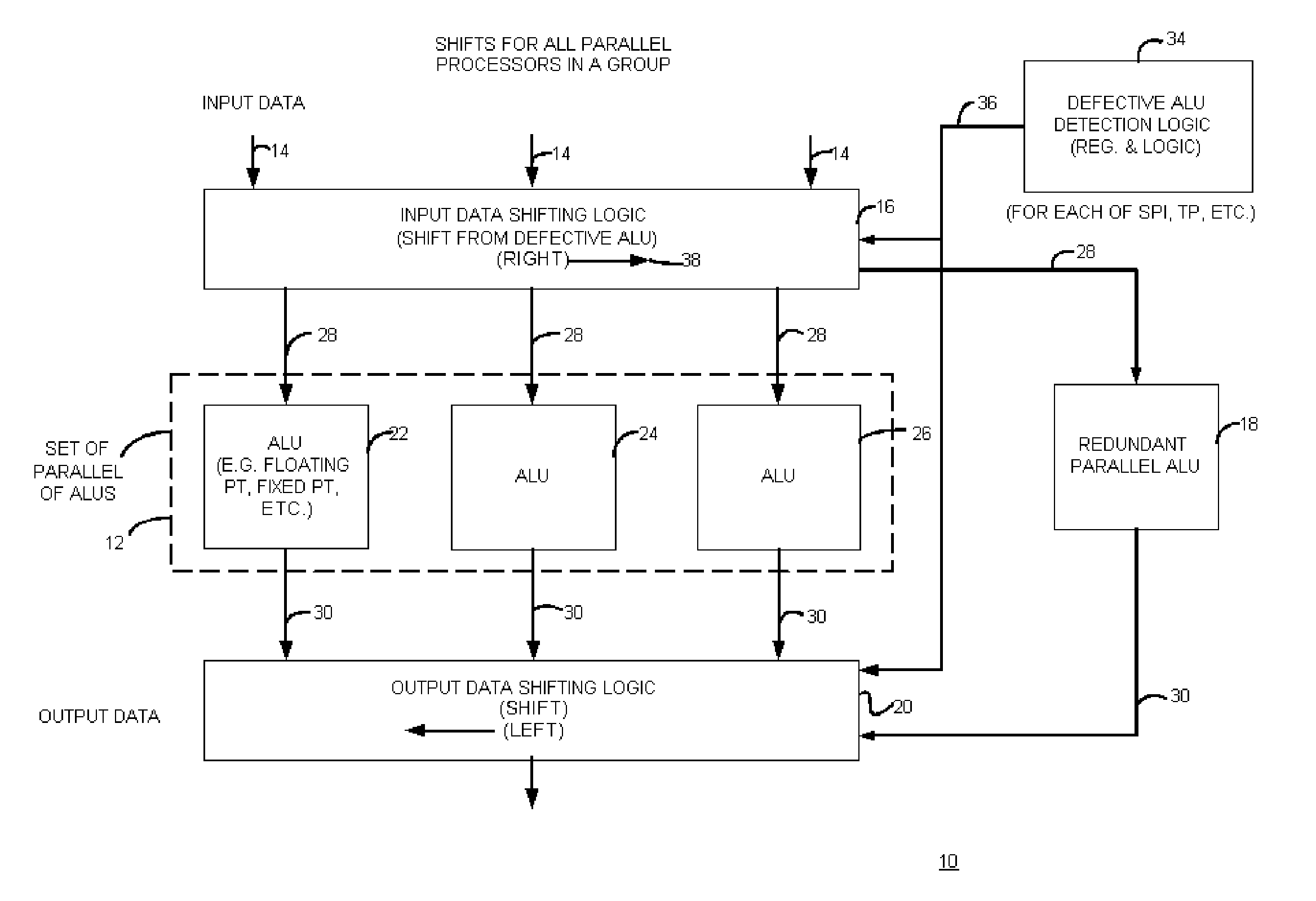
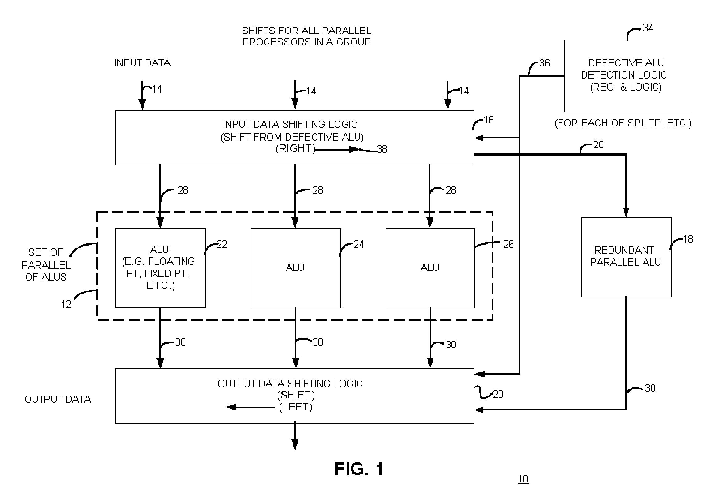
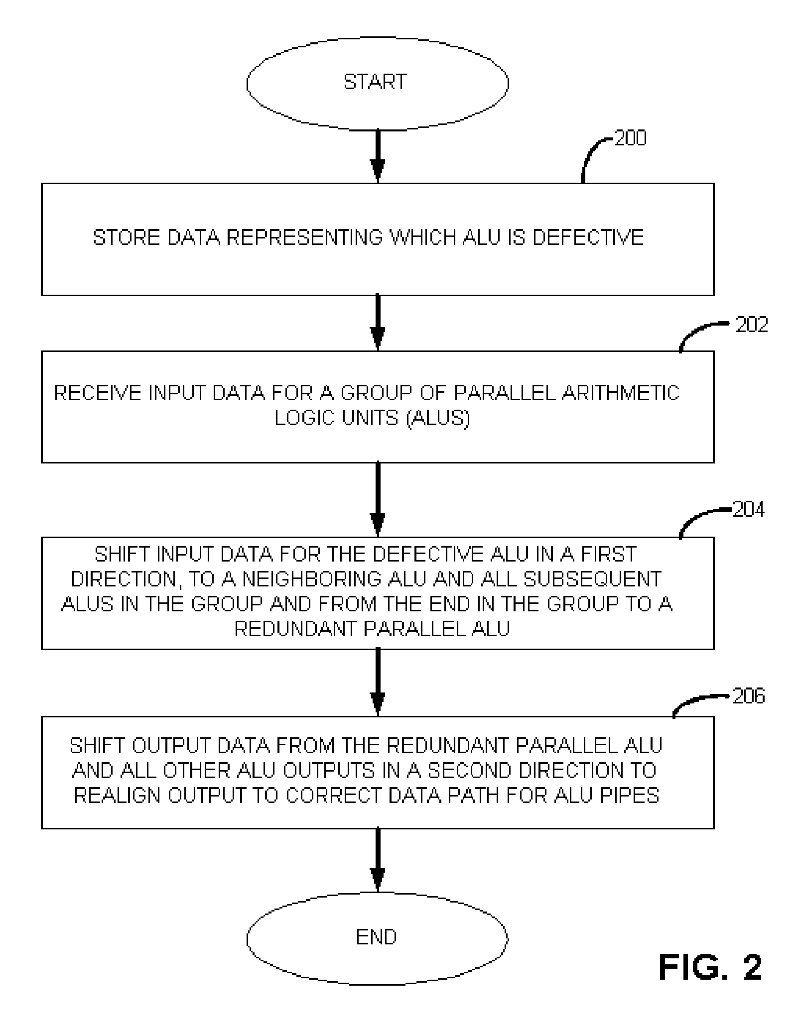
[0019] Briefly, an apparatus with circuit redundancy includes a set of parallel arithmetic logic units (ALUs), a redundant parallel ALU, input data shifting logic that is coupled to the set of parallel ALUs and that is operatively coupled to the redundant parallel ALU. The input data shifting logic shifts input data for a defective ALU, in a first direction, to a neighboring ALU in the set. When the neighboring ALU is the last or end ALU in the set, the shifting logic continues to shift the input data for the end ALU that is not defective, to the redundant parallel ALU. The redundant parallel ALU then operates on a unit of work for the defective ALU, but not necessary the same data set as the defective unit unless it was the last of a set of ALUs. Output data shifting logic is coupled to an output of the parallel redundant ALU and all other ALU outputs to shift the output data in a second and opposite direction than the input shifting logic, to realign output of data for continued p...


PUM


Abstract

An apparatus with circuit redundancy includes a set of parallel arithmetic logic units (ALUs), a redundant parallel ALU, input data shifting logic that is coupled to the set of parallel ALUs and that is operatively coupled to the redundant parallel ALU. The input data shifting logic shifts input data for a defective ALU, in a first direction, to a neighboring ALU in the set. When the neighboring ALU is the last or end ALU in the set, the shifting logic continues to shift the input data for the end ALU that is not defective, to the redundant parallel ALU. The redundant parallel ALU then operates for the defective ALU. Output data shifting logic is coupled to an output of the parallel redundant ALU and all other ALU outputs to shift the output data in a second and opposite direction than the input shifting logic, to realign output of data for continued processing, including for storage or for further processing by other circuitry.

Description

RELATED APPLICATIONS [0001] This application claims the benefit of U.S. Provisional Application Ser. No. 60 / 600,942 filed Aug. 11, 2004, entitled “APPARATUS WITH REDUNDANT CIRCUITRY AND METHOD THEREFOR”, having as an inventors Michael Mantor, Ralph Clayton Taylor and Robert Scott Hartog, and owned by instant assignee and hereby incorporated by reference in its entirety.FIELD OF THE INVENTION [0002] The invention relates generally to apparatus that employ redundant circuitry, and more particularly to apparatus that employ redundant circuitry that perform arithmetic operations and methods therefor and / or apparatus that employ multiple parallel arithmetic logic units. BACKGROUND OF THE INVENTION [0003] Hardware redundancy may be employed in various circuits by including extra copies of a hardware block or circuit that can replace original versions of a same circuit if original versions are found to be defective in silicon. Production yields can be then be increased by including extra c...

Claims


Application Information

Patent Timeline
Patent Type & Authority Applications(United States)
IPC IPC(8): G06F7/38
CPCG06F11/2028G06F11/2048G06F11/2038
Inventor MANTOR, MICHAELTAYLOR, RALPH CLAYTONHARTOG, ROBERT SCOTT
Owner ATI TECH INC
Learn More