Apparatus for operating a feed device for fiber material, for example, a hopper feeder

a technology of hopper feeder and feed device, which is applied in the direction of control device of conveyor, conveyor, mechanical conveyor, etc., can solve the problems of discontinuous control of the drive arrangement of the conveyor belt and/or the transition belt, and achieve the effect of avoiding or reducing the number of problems

Inactive Publication Date: 2006-03-16
TRUETZSCHLER GMBH & CO KG
View PDF11 Cites 5 Cited by
  • Summary
  • Abstract
  • Description
  • Claims
  • Application Information

AI Technical Summary

Benefits of technology

[0004] It is an aim of the invention to produce an apparatus of the kind described initially that avoids or mitigates the said disadvantages and in particular in a simple manner enables fibre material to be supplied to the hopper feeder without interruption to production.
[0011] The features according to the invention enable the transition belt to be moved independently of the reserve belt. The transition belt can thus deliver fibre material to the conveyor belt so that the mixing chamber does not run without load. At the same time, that is, as the transition belt is running, the reserve belt can be loaded with fibre bales whilst at a standstill. Running with no load is in this manner advantageously reliably avoided, and re-loading of the reserve belt can be effected within an adequate buffer time. By isolating the reserve belt, the belt flight that is feeding fibre to the mixing chamber can be moved independently of the reserve belt. A sensor preferably monitors the end of the belt flight that is feeding fibre material and indicates when the reserve belt has run empty. As the last bale portion present on the belt flight that is feeding fibre material is being worked off in the normal way, the upstream reserve belt can be reloaded independently of the process still under way.

Problems solved by technology

Advantageously, the drive arrangement for the conveyor belt and / or the transition belt is discontinuously controllable.

Method used


Image

  • Apparatus for operating a feed device for fiber material, for example, a hopper feeder
  • Apparatus for operating a feed device for fiber material, for example, a hopper feeder

Examples


Embodiment Construction

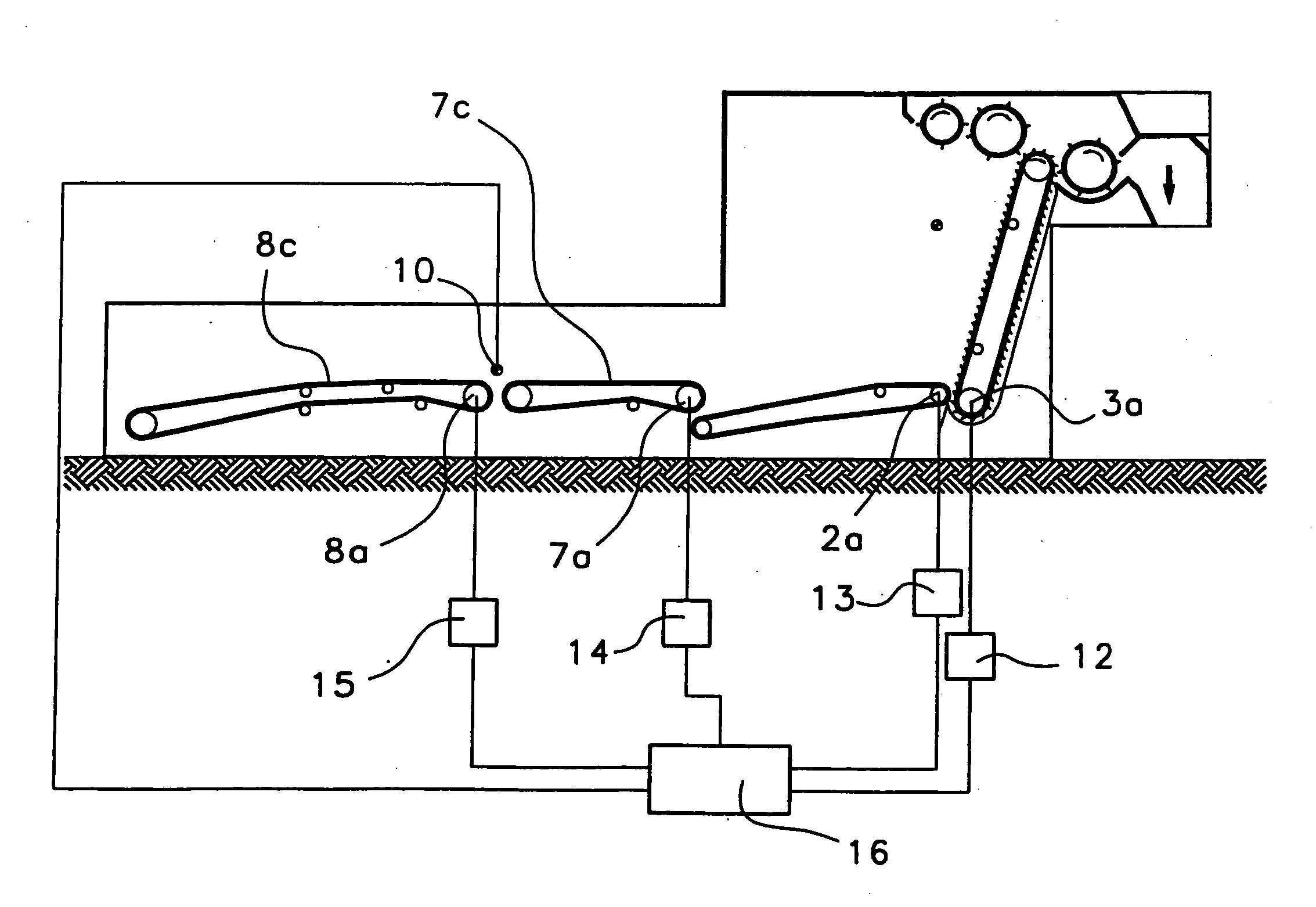
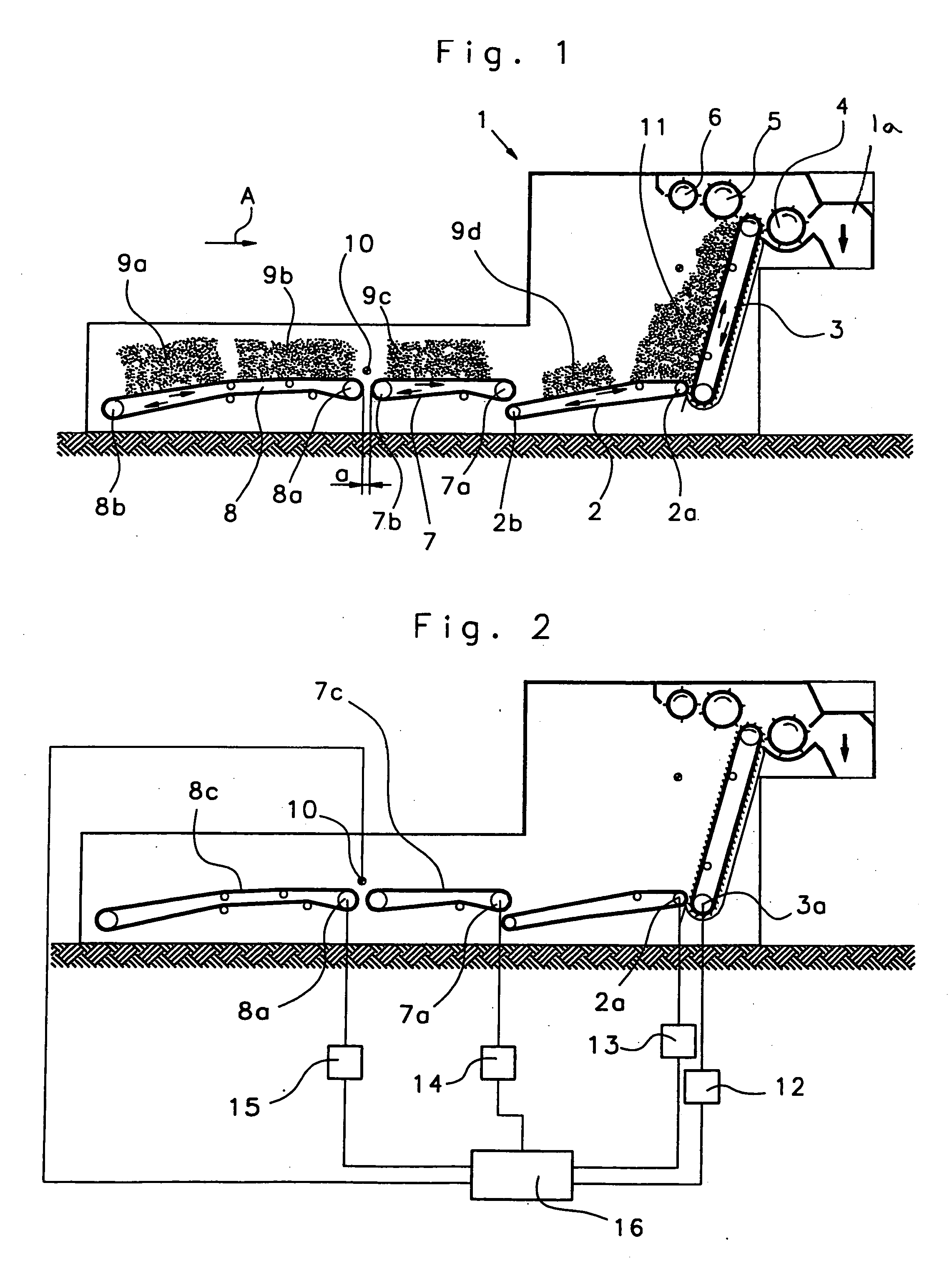
[0016] With reference to FIG. 1, a hopper feeder 1 has a conveyor belt 2 (feed apron), spiked lattice 3 (spiked apron), stripping roller 4, evener roller 5 and clearer roller 6. Arranged upstream of the conveyor belt 2, viewed in a direction opposite to the conveying direction A, are a transition belt 7 and a reserve belt 8 (feed belt or feed table). The front guide roller 7a of the transition belt 7 is arranged somewhat above the rear guide roller 2b of the conveyor belt 2, so that the ends of the two belts overlap. The fibre material 9c falls from above onto the conveyor belt 2. The front guide roller 8a of the feed belt 8 and the rear guide roller 7b of the transition belt 7 are arranged relative to one another so that the upper belt flights of the feed belt 8 and the transition belt 7 lie substantially at the same level, thus facilitating transfer of the fibre bales 9b onto the transition belt 7. A narrow gap a is left between the ends of the reserve belt 8 and of the transition...


PUM

PropertyMeasurementUnit
sizeaaaaaaaaaa
timeaaaaaaaaaa

Abstract

In an apparatus for operating a feed device for fibre material, for example, a hopper feeder, there is provided a drivable, endless conveyor belt guided around two rotatable rolls. The conveyor belt is associated at one end, looking in the conveying direction, with an endless, upwardly inclined spiked lattice. Upstream of the other end of conveyor belt, looking in the opposition direction to the conveying direction, there is arranged an endless feed belt (reserve belt) for receiving fibre bales or the like. To convey fibre material to the hopper feeder in a simple manner, without interruption to production, there is arranged between the conveyor belt and the reserve belt 8a continuously circulating transition belt, and the absence of fibre material on the reserve belt is detectable.

Description

CROSS REFERENCE TO RELATED APPLICATION [0001] This application claims priority from German Patent Application No. 10 2004 042 443.8 dated Aug. 31, 2004, the entire disclosure of which is incorporate herein by reference. BACKGROUND OF THE INVENTION [0002] The invention relates to an apparatus for operating a feed device for fibre material. [0003] In practice, in the manufacture of nonwoven products, hopper feeders are used for opening the bales of raw fibre. In one known form of hopper feeder, a drivable, endless conveyor belt guided around two rotatable rolls is provided. The conveyor belt is associated at one end, looking in the conveying direction, with an endless, upwardly inclined spiked lattice, and upstream of the other end of the conveyor belt, looking opposite to the conveying direction, there is an endless feed belt (reserve belt), on which fibre bales or the like can be placed. The bales of raw fibre supplied to the process are in many cases presented unseparated, in the f...

Claims


Application Information

Patent Timeline
Patent Type & Authority Applications(United States)
IPC IPC(8): B65G43/00B65G37/00B65G25/00B65G29/00D01G7/08
CPCD01G7/08
Inventor RUBENACH, BERNHARD
Owner TRUETZSCHLER GMBH & CO KG
Why Eureka
Try Eureka