

Tubular linear motor for electrical discharge machine
- Summary
- Abstract
- Description
- Claims
- Application Information
AI Technical Summary
Benefits of technology
Problems solved by technology
Method used
Image

Examples
Embodiment Construction
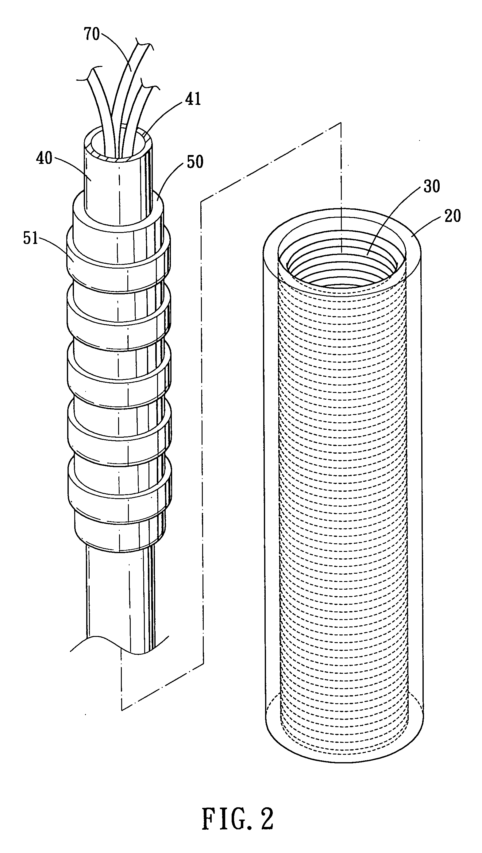
[0017] Referring to FIGS. 2 and 3, a tubular linear motor in accordance with the present invention is shown and generally including: a stator 20, a set of coils 30, a central shaft 40 and a forcer 50.
[0018] The stator 20 is a hollow tubular member and fixed at a predetermined position of an electrical discharge machine.
[0019] The set of coils 30 are disposed on the internal surface of the stator 20, the direction of the electric energy of the set of coils 30 is controlled by a control system of the electrical discharge machine.
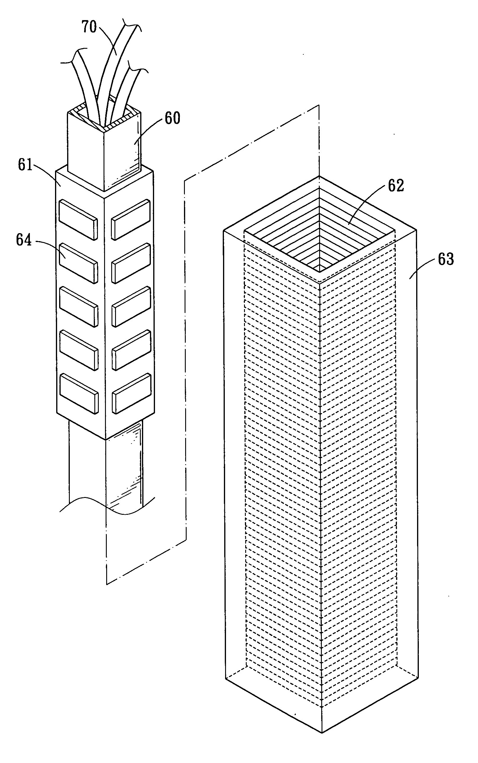
[0020] The central shaft 40 is a hollow tubular member interiorly defined with a space 41, in which provided different kinds of wires 70. The central shaft 40 is located at the axial center of the stator 20 for discharging electric energy.
[0021] The forcer 50 is also a hollow tubular member slidably mounted onto the outer peripheral surface of the central shaft 40 and is provided with a vertical tool electrode (exemplary but not limiting). A plurality of p...
PUM
 Abstract
Description
Claims
Application Information