Heat retaining sleeve

Active Publication Date: 2006-03-16
ABL IP HLDG
View PDF1 Cites 14 Cited by
  • Summary
  • Abstract
  • Description
  • Claims
  • Application Information

AI Technical Summary

Benefits of technology

[0013] Therefore, it can be seen that it is a primary object of the invention to provide an heat retaining sleeve for linear fluorescent lamps, such as T-5 lamps, used in indirect and indirect-direct lighting fixtures which is effective in increasing the l

Problems solved by technology

However, T-5 lamps in indirect lighting fixtures operate at a temperature which is cooler than the optimum and therefore do not produce maximum lumen output.
This sleeve has pro

Method used


Image

  • Heat retaining sleeve
  • Heat retaining sleeve
  • Heat retaining sleeve

Examples


first embodiment

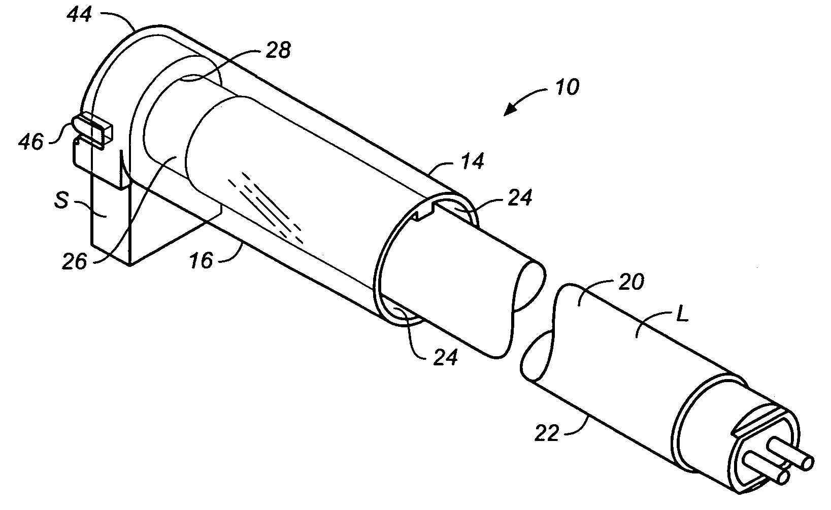
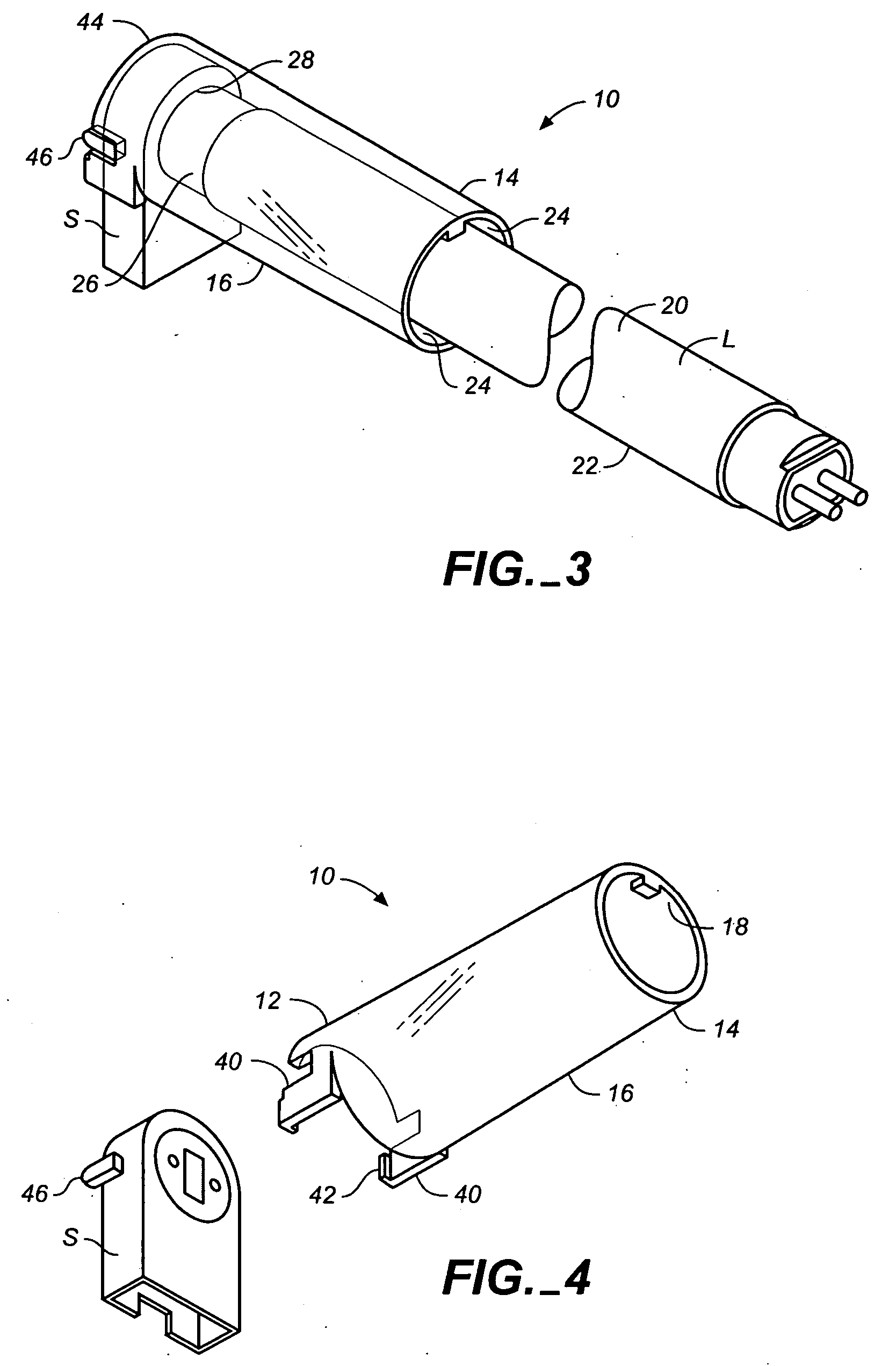
[0039] The sleeve body 16, as mentioned above, extends from the base end 12 over the lamp body 22. the sleeve body 16 as seen in FIGS. 3-8 is a full cylinder. The full cylinder embodiment is appropriate for use in a direct-indirect lighting fixtures where the lamp body is not crowded by a bottom reflector surface. The full cylinder embodiment completely encircles the lamp body 22 to form a cylindrical heat retaining gap 24 between the inner surface 18 of the sleeve body 16 and the lamp body 22. A downwardly depending projection 50 on the upper part of the distal end 14 of the sleeve body 16 supports the length of the sleeve body over and in concentric alignment with the lamp body in position to form the heat retaining gap 24. This works well in fixtures in which the lamp sockets are upwardly oriented. It will be appreciated that in lighting fixtures in which the lamp sockets are downwardly directed, the projection 50 will be disposed on the opposite side of the sleeve. Those of skil...

second embodiment

[0041] the sleeve comprises a partial cylinder sleeve body 60 seen in FIGS. 9-14. The partial cylinder 60, preferably for use in indirect lighting fixtures characterized by a bottom reflector plate (not illustrated) which tends to crowd the lamp L leaving insufficient room for installation of the full cylinder embodiment of the sleeve body shown in FIGS. 3-8. The partial cylinder sleeve body 60 includes an elongated opening 62 defined by substantially parallel edge portions 64 extending longitudinally along the bottom of the sleeve body 60 adjacent the fixture's bottom reflector plate (not shown). The partial cylinder 60 advantageously cooperates with the bottom reflector plate to form a substantially cylindrical heat retaining gap 66 around most of the lamp body except for a relatively small portion at the bottom. Along each edge portion 64 of the opening is an inwardly extending rib 70 traversing the length of the opening 64. Each rib extends from the inner surface 72 of the sleev...

third embodiment

[0044] a heat retaining sleeve according to the invention is generally indicated by numeral 88 in FIGS. 15-17. In this embodiment, the sleeve, which covers a single lamp L in an indirect lighting fixture and is of a generally square shape, has a sleeve body 89 with a distal end 91 that extends a sufficient distance to reach the hot spot of the lamp. A base end 93 of the sleeve has a downwardly depending projection 90 for fitting into a cooperating aperture (not shown) in the lighting fixture. A tab 92, which extends laterally from the base end, has a hole 96 for accepting a threaded fastener for securing the sleeve 88 to the lighting fixture. The sleeve 88 includes generally parallel side walls 98 and a top wall 100. In alternate embodiments, all or portions of the lengths of the bottom edges 102 of the side walls 98 may be higher to accommodate the elements of the lighting fixture in which the sleeve 88 is mounted, particularly bottom reflector plates which may angle up from the bo...


PUM


Abstract

A heat retaining sleeve for raising the cold spot temperature of a fluorescent lamp is comprised of a base end, a distal end, and a sleeve body sized and shaped to fit over the end of a fluorescent lamp or lamps where the lamp's cold spot exists. The sleeve creates a heat retaining air gap between the inner surface of the sleeve body and the lamp end or ends with the cold spot, and has sufficient length to so that, when fitted over the lamp end or ends, the cold spot temperature is elevated to a temperature that increase the lumen output of the fitted fluorescent lamp or lamps.

Description

CROSS-REFERENCE TO RELATED APPLICATIONS [0001] This application claims the benefit of U.S. Provisional Application No. 60 / 584,614, filed Jun. 30, 2004.BACKGROUND OF THE INVENTION [0002] This application relates to a heat-retaining sleeve for a fluorescent lamp for increasing the temperature of the ‘cold spot’ of the lamp to optimize the lumen output of the lamp. [0003] All fluorescent lamps have an optimum temperature at which maximum lumen output is produced. The lumen output of fluorescent lamps is related to two characteristic temperatures: the ambient temperature, and the “cold spot” temperature. The ambient temperature is the temperature of the air immediately surrounding the lamp. The “cold spot” temperature is the temperature of the lamp itself at its coldest point, generally situated behind the electrode at the brand-stamp end of the lamp. Maximum lumen output is experienced when either the ambient temperature or the cold spot temperature reaches an optimum temperature. Cert...

Claims


Application Information

Patent Timeline
IPC IPC(8): H01J61/52
CPCF21V17/164F21V25/00H01J61/523H01J61/24F21Y2103/00
Inventor NGAI, PETER Y.Y.ZHANG, JOHNLY, HUE
Owner ABL IP HLDG
Why Eureka
Try Eureka