Coding apparatus and imaging apparatus

Active Publication Date: 2006-03-16
PANASONIC SEMICON SOLUTIONS CO LTD
View PDF2 Cites 3 Cited by
  • Summary
  • Abstract
  • Description
  • Claims
  • Application Information

AI Technical Summary

Benefits of technology

[0027] According to this construction, the generating unit uses the intermediate value to judge whether the first subtraction data is included in the code presence sub-group. In this way, the generating unit can perform, in parallel, the generation of the first subtraction data, and the judgment by using the intermediate value. In other words, a mechanism to make the judgment by using the intermediate value and a mechanism to generate t

Problems solved by technology

While shortening a processing cycle, however, the variable-length coding method disclosed in the patent document 1 has a problem

Method used


Image

  • Coding apparatus and imaging apparatus
  • Coding apparatus and imaging apparatus
  • Coding apparatus and imaging apparatus

Examples


Example

[0149] The following describes an imaging system 100 relating to a first embodiment of the present invention.

[0150] As shown in FIG. 1, the imaging system 100 relating to the first embodiment of the present invention is constituted by an optical system 101, a sensor 102, a converting circuit 103, an image processing circuit 104, a recording and transmitting system 105, a playback system 106, a timing control circuit 108, and a system control circuit 107.

[0151] The optical system 101 includes a lens, a color filter, and the like. The optical system 101 collects light that enters the imaging system 100. The sensor 102 is formed by using an imaging element such as a charge coupled device (CCD). The sensor 102 converts an amount of the light that enters the imaging system 100 through the optical system 101, into an electric charge, and stores the electric charge. Also, the sensor 102 outputs the stored electric charge to the converting circuit 103, in synchronization with a clock sign...

Example

2. Second Embodiment

[0270] The following describes an imaging system relating to a second embodiment of the present invention.

[0271] The imaging system relating to the second embodiment is constituted by an optical system, a sensor, a converting circuit, an imaging processing circuit, a recording and transmitting system, a playback system, a timing control circuit, and a system control circuit, similarly to the imaging system 100 relating to the first embodiment. Except for a variable-length coding circuit 200b included in the recording and transmitting system, the imaging system relating to the second embodiment has the same construction as the imaging system 100 relating to the first embodiment. Accordingly, the following only describes the variable-length coding circuit 200b, which characterizes the second embodiment.

[0272] 2.1 Variable-Length Coding Circuit 200b

[0273] The variable-length coding circuit 200b first judges whether a type of a code to be assigned to a combinatio...

Example

3. THIRD Embodiment

[0352] The following describes an imaging system relating to a third embodiment of the present invention.

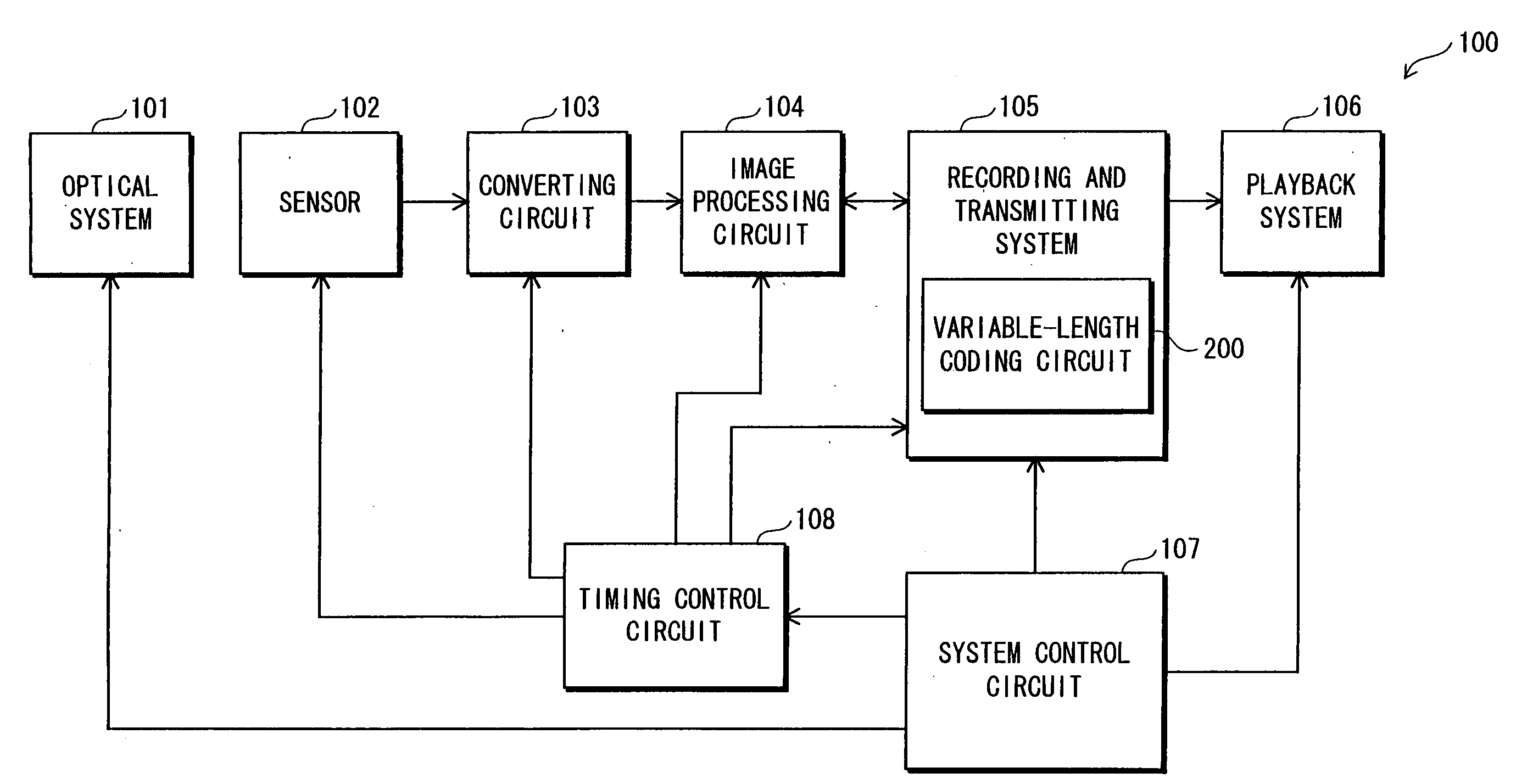
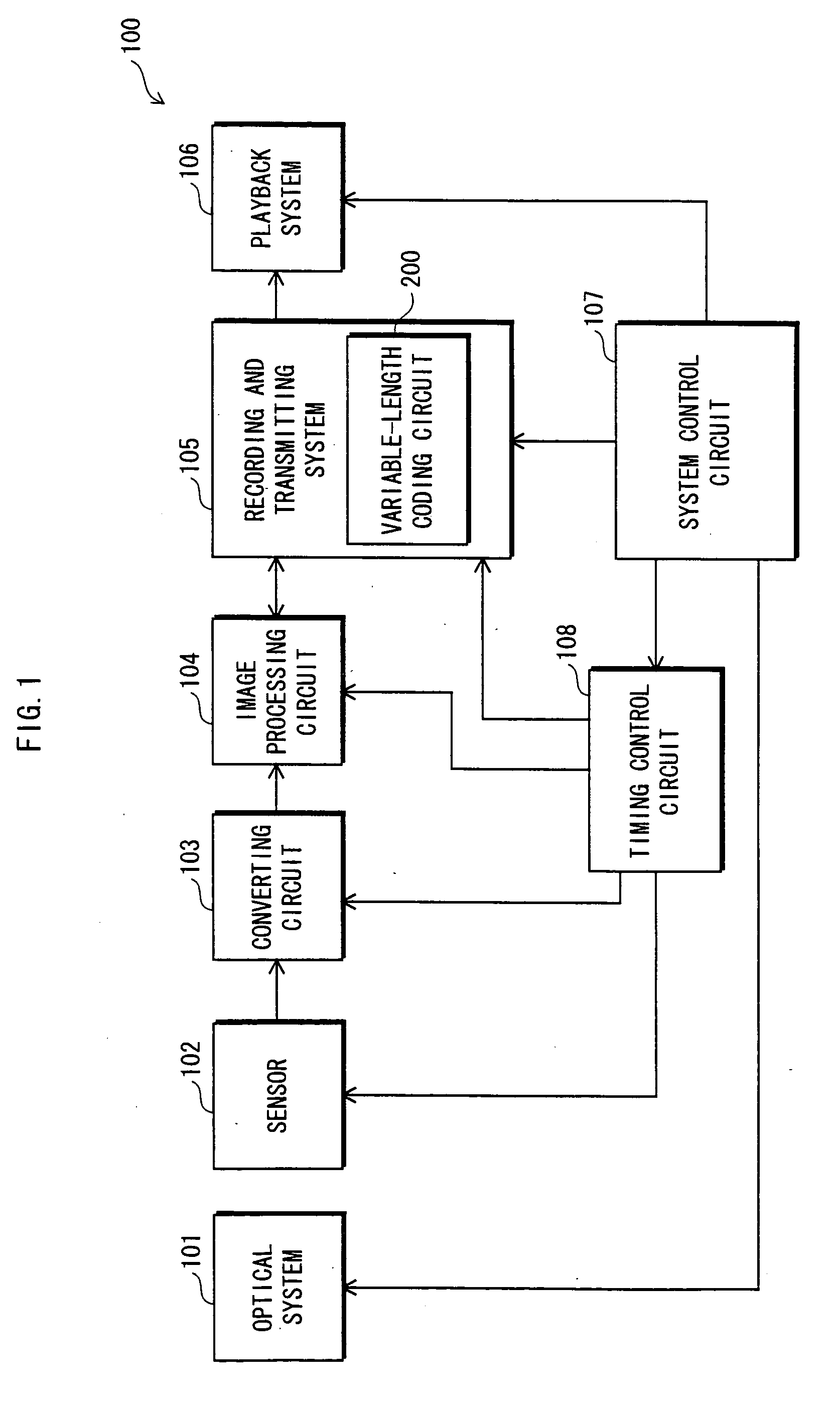
[0353] Similarly to the imaging system 100 relating to the first embodiment, the imaging system relating to the third embodiment is constituted by an optical system, a sensor, a converting circuit, an image processing circuit, a recording and transmitting system, a playback system, a timing control circuit, and a system control circuit. Except for a variable-length coding circuit 200c included in the recording and transmitting system, the third embodiment is the same as the first embodiment. Accordingly, the following only describes the variable-length coding circuit 200c.

3.1 Variable-Length Coding Circuit 200c

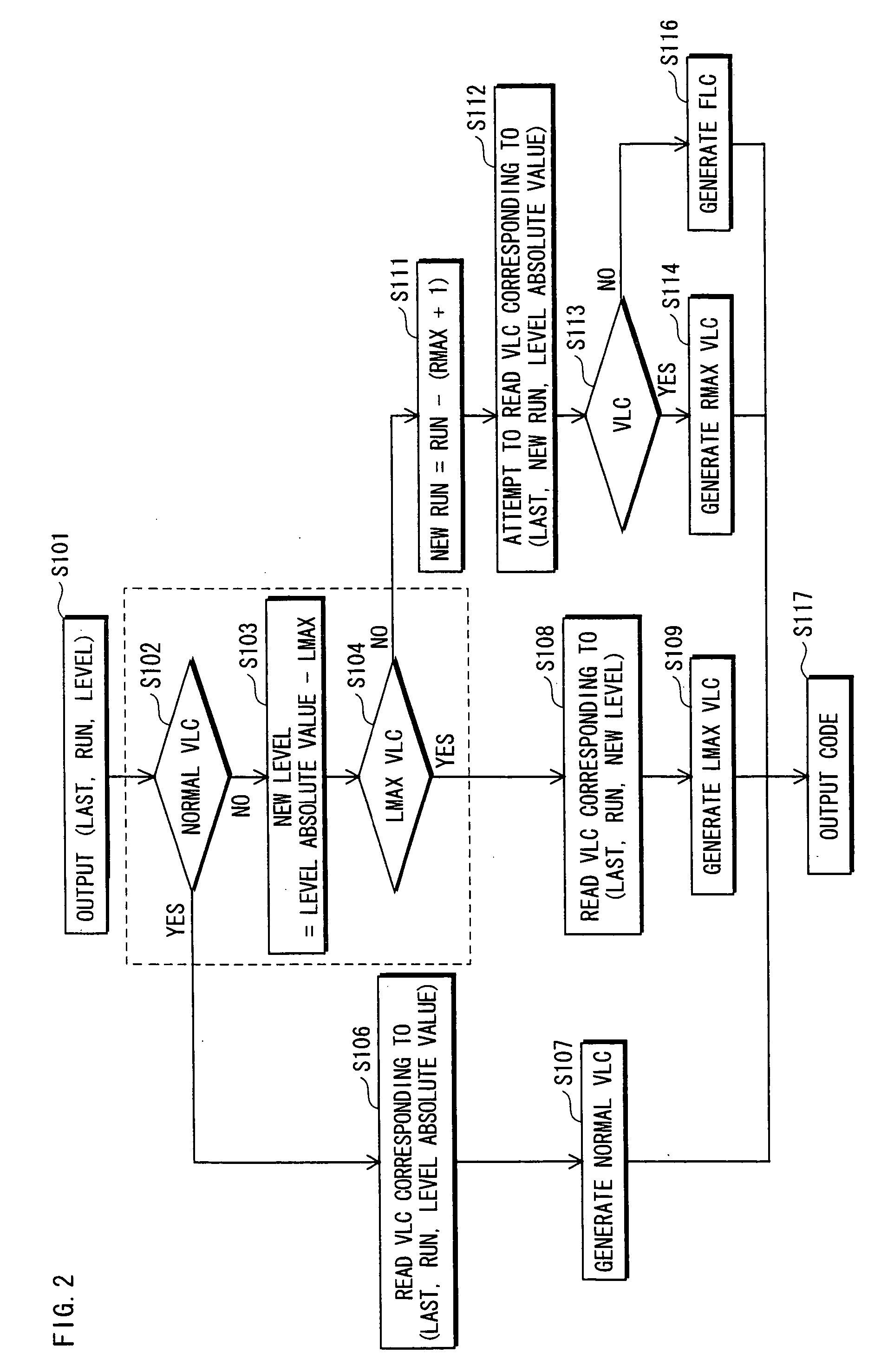
[0354] The variable-length coding circuit 200c judges which one of a normal VLC, an LMAX VLC, an RMAX VLC, and an FLC is to be assigned to a combination (Last, Run, Level), and generates a code based on the result of the judgment. The following descr...


PUM


Abstract

The present invention aims to provide a variable-length coding apparatus that achieves a short processing cycle without causing an increase in circuit scale. Such a variable-length coding apparatus judges whether a VLC table has a variable-length code (VLC) corresponding to a combination (Last, Run, Level), by using an LMAX and an RMAX for the combination (Last, Run, Level). Based on the result of the judgment, the variable-length coding apparatus generates and outputs a code assigned to the combination (Last, Run, Level).

Description

[0001] This application is based on an application No. 2004-249300 filed in Japan, the content of which is hereby incorporated by reference. BACKGROUND OF THE INVENTION [0002] (1) Field of the Invention [0003] The present invention relates to a variable-length coding technique. [0004] (2) Related Art [0005] As digital still and video cameras have become widely used and communication technologies have advanced, image data compressing techniques are increasingly utilized. A representative example of such compressing techniques is the ISO-standardized Moving Picture Experts Group (MPEG) format. [0006] The MPEG technique realizes image data compression in the following manner. A frame is divided into a plurality of blocks each consisting of a plurality of pixels, based on intraframe correlation. After this, the data in each block is subjected to a discrete cosine transform (DCT) operation, which is one of orthogonal transformations, quantized, and then variable-length coded. [0007] The ...

Claims


Application Information

Patent Timeline
IPC IPC(8): H03M7/40H03M7/46H04N19/103H04N19/136H04N19/182H04N19/196H04N19/60H04N19/625H04N19/91H04N19/93
CPCH03M7/40
Inventor NAGATA, TAICHIKITAMURA, SHINJITANAKA, YASUHARA
Owner PANASONIC SEMICON SOLUTIONS CO LTD
Why Eureka
Try Eureka