Service provision system and automatic photography system
- Summary
- Abstract
- Description
- Claims
- Application Information
AI Technical Summary
Benefits of technology
Problems solved by technology
Method used
Image
Examples
first embodiment
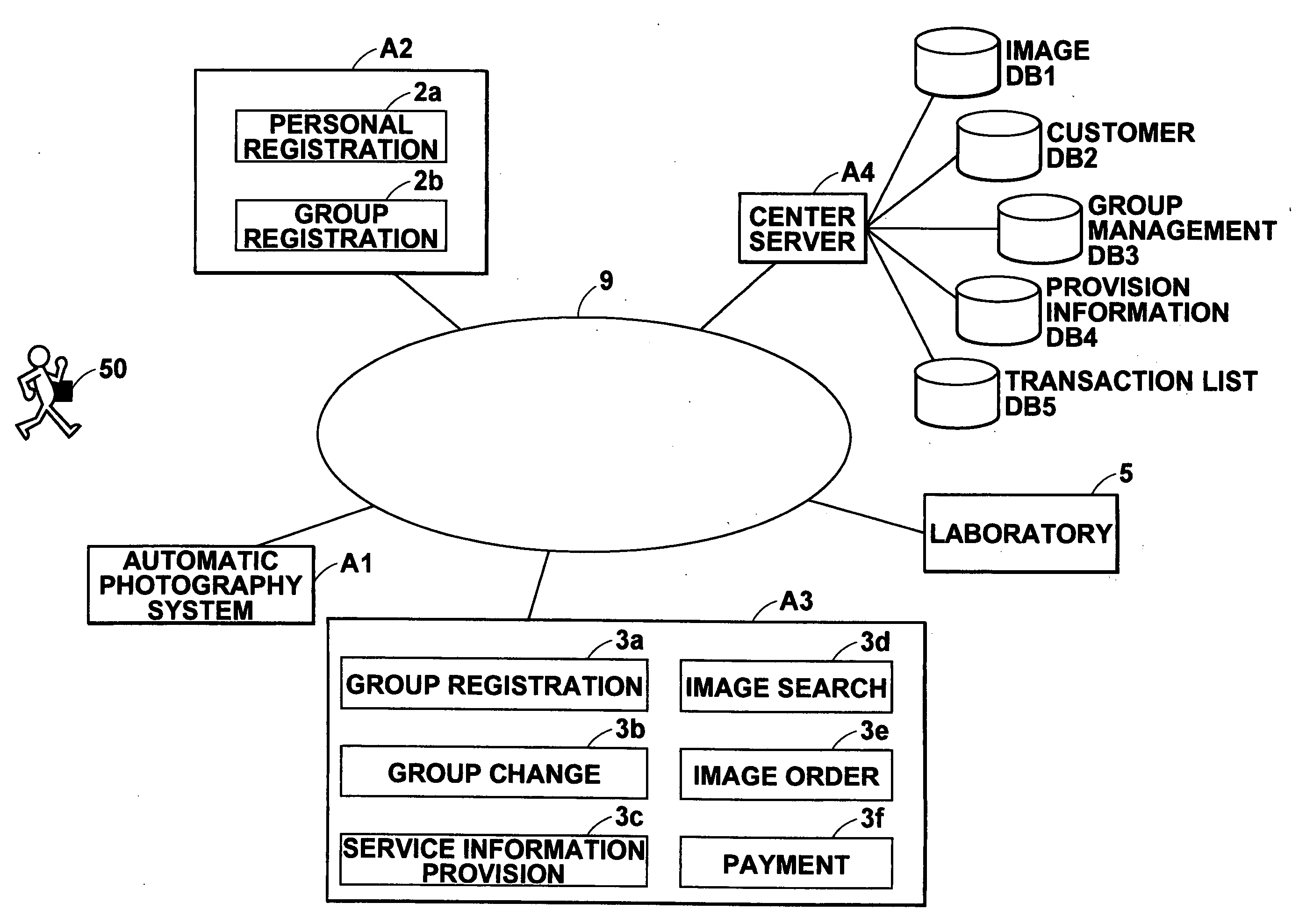
[0207] A procedure carried out when the service information is provided to the customer U will be described next. FIG. 19 is a flow chart showing the procedure carried out for providing the service information in the The procedure carried out by the service information provision unit 3c of the terminal A3 will be described here. The control unit 35 of the terminal A3 causes the first communication unit 31 to constantly transmit the inquiry signal (Step S1), and monitors whether or not the first communication unit 31 has received the reply signal from the wireless tag 50 of the customer U (Step S2). If a result at Step S2 is affirmative, the tag ID included in the reply information represented by the reply signal is sent from the second communication unit 36 to the center server A4 (Step S3). If the result at Step S2 is negative, the procedure returns to Step S1.
[0208] In the center server A4, the communication unit 41 receives the tag ID (Step S4), and the control unit 44 refers to...
second embodiment
[0244] An automatic photography system in a theme park system of the present invention will be described next.
[0245]FIG. 25 is a block diagram showing the automatic photography system in the second embodiment.
[0246] An automatic photography system B1 in FIG. 25 comprises a plurality of photography devices B140 for automatically photographs customers as a subject, a wireless tag 50 held by each of the customers and transmitting identification information, and a center server B4 for storing an image data set obtained by each of the photography devices B140.
[0247] A long-range RFID tag having a battery and communicable within several meters, for example, may be used as the wireless tag 50. The wireless tag 50 is distributed to each of members in a group using services by the automatic photography system B1. The wireless tag 50 stores a customer ID (a tag ID) specific to each of the customers as the member of the group. Customer information necessary for the services, such as the name...
third embodiment
[0271]FIG. 30 is a block diagram showing the automatic photography system in the In an automatic photography system C1 in this embodiment, each of photography devices C140 comprises a digital camera 142 for photographing a subject, antennas C143A, C142B, and C143C for detecting a wireless tag 50 held by the subject and for communicating with the wireless tag 50, a speaker 144 as notification means, and a computer C141 connected to the digital camera 142, the antennas C143A, C143B, and C143C, and the speaker 144. The photography devices C140 are installed in a theme park having the automatic photography system C1 therein.
[0272]FIG. 31 shows an example of installation of one of the photography devices C140 in the theme park. The digital camera 142 is installed at a position where a predetermined photography spot in the theme park can be photographed. The antenna C143A is installed at a position where the wireless tag 50 in a photography range (range a) of the digital camera 142 can b...
PUM
 Abstract
Description
Claims
Application Information
 - R&D
- Intellectual Property
- Life Sciences
- Materials
- Tech Scout
- Unparalleled Data Quality
- Higher Quality Content
- 60% Fewer Hallucinations
Browse by: Latest US Patents, China's latest patents, Technical Efficacy Thesaurus, Application Domain, Technology Topic, Popular Technical Reports.
© 2025 PatSnap. All rights reserved.Legal|Privacy policy|Modern Slavery Act Transparency Statement|Sitemap|About US| Contact US: help@patsnap.com


