Magnetic spring actuator device

a technology of actuator device and magnetic spring, which is applied in the direction of vibration dampers, electrical appliances, basic electric elements, etc., can solve problems such as affecting performance or affecting performan

Inactive Publication Date: 2006-03-16
GOMBINSKY MOSHE +1
View PDF13 Cites 17 Cited by
  • Summary
  • Abstract
  • Description
  • Claims
  • Application Information

AI Technical Summary

Benefits of technology

[0025] Further according to preferred embodiments of the present invention, the magnetic spring actuator also comprises a stopper. The stopper ensur

Problems solved by technology

Also, the magnetic force does not change over time in contrast to springs which can change over time thus resulting in compromised o

Method used


Image

  • Magnetic spring actuator device
  • Magnetic spring actuator device
  • Magnetic spring actuator device

Examples


Embodiment Construction

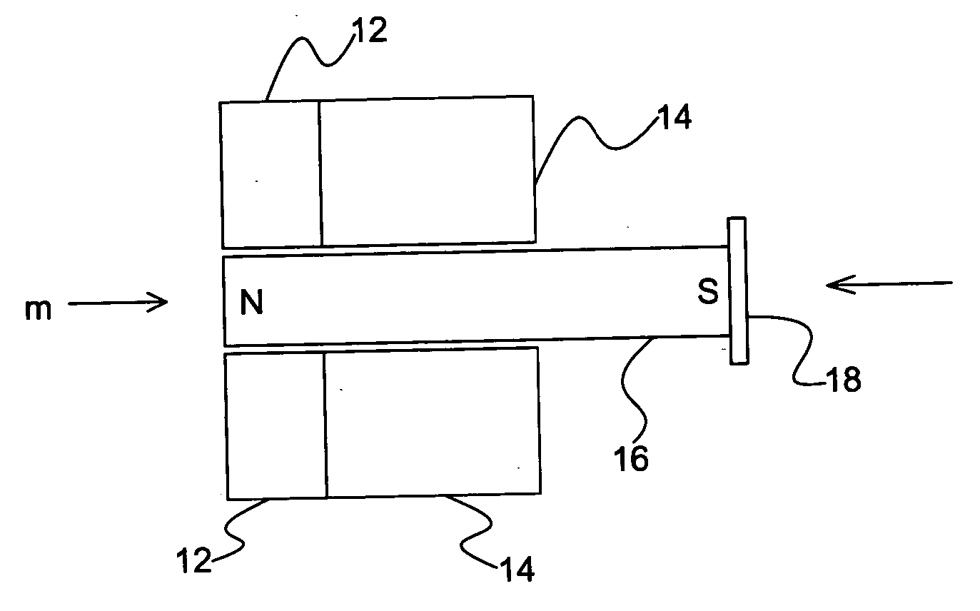
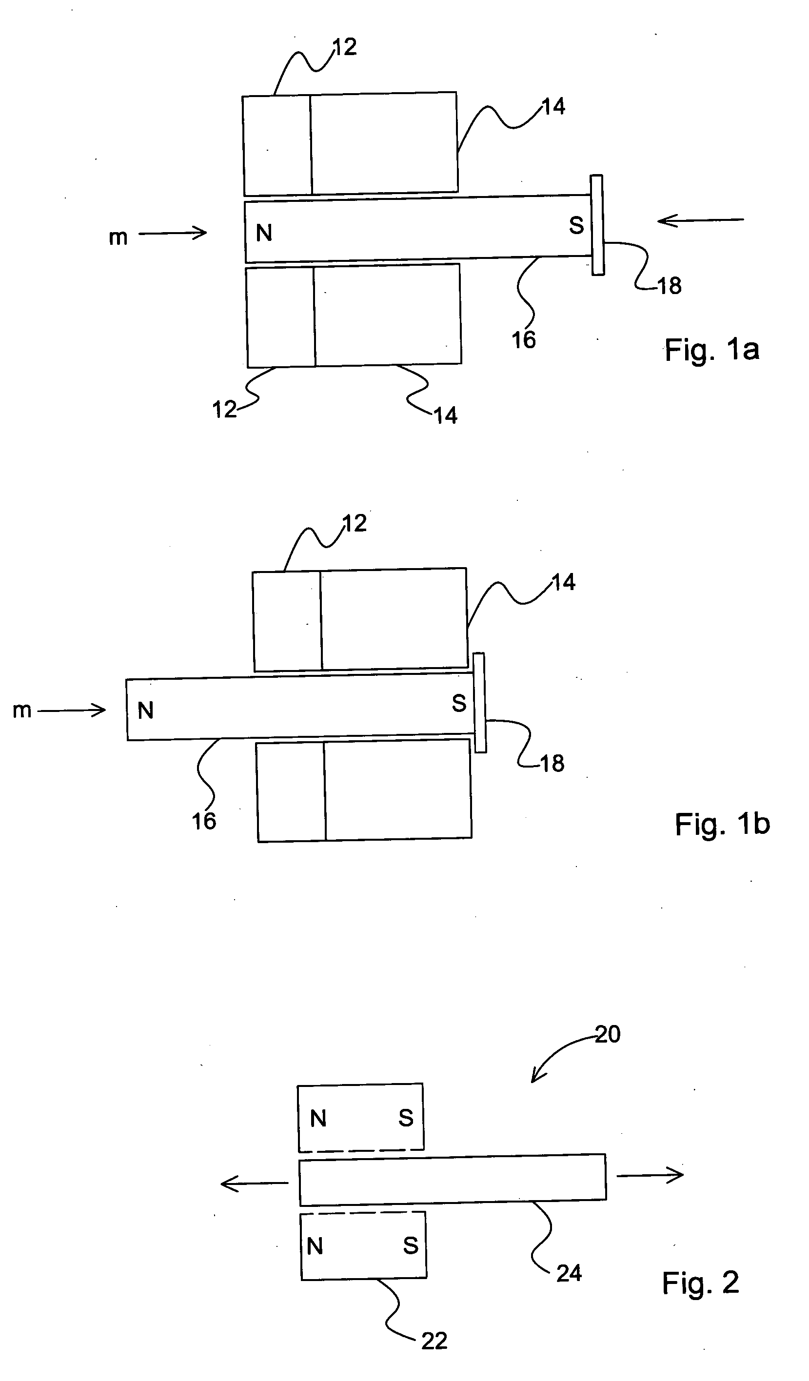
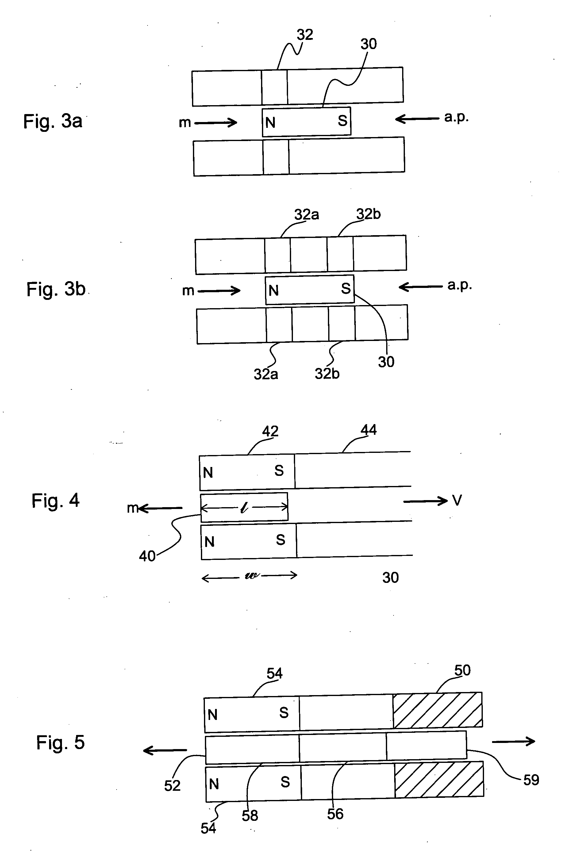
[0066] The invention discloses a magnetic spring actuator comprising a ring, a piston movably disposed inside of the ring, and a non-magnetic holding cylinder. At least one of the ring and the piston is magnetic. Due to a magnetic force caused by at least one of the ring and the piston, the piston is initially located in a first position with respect to the ring. Application of an outside force results in movement of the piston to a second position with respect to the ring. The magnetic force produces a return force for causing the piston to return to the first position with respect to the ring.

[0067] Alternatively, the piston can be fixed and the ring can be adapted for moving with respect to the piston in a similar manner.

[0068] The term “a.p.” appearing in the drawings refers to air pressure. “N” and “S” refer to north and south magnetic poles. The arrows in the Figures indicate directions of the initial applied force and of the magnetic return force, and, consequently, the dir...


PUM


Abstract

A magnetic spring actuator comprising a ring, a piston movably disposed inside of the ring, and a-non-magnetic holding cylinder. At least one of the ring and the piston is magnetic. Due to a magnetic force caused by at least one of the ring and the piston, the piston is initially located in a first position with respect to the ring. Application of an outside force results in movement of the piston to a second position with respect to the ring. The magnetic force produces a return force for causing the piston to return to the first position with respect to the ring. Alternatively, the piston can be fixed and the ring can be adapted for moving with respect to the piston in a similar manner. A bi-metal coil spring may be wound around the piston.

Description

FIELD OF THE INVENTION [0001] The present invention relates to a magnetic spring actuator device. The invention can be used as a common spring in almost every application in which springs are employed, under the condition that the magnetism does not disturb other aspects of the technology. The magnetic spring actuator is especially useful in the fields of pneumatic and electromagnetic actuation. BACKGROUND OF THE INVENTION [0002] Prior art patent EP1420164 describes a simplified magnetizable piston slidable in a cylinder and moved by magnetic coupling to an external magnetic element which moves along the cylinder and is actuated via an external actuator. [0003] Prior art patent DE 10147064 describes a vibrator for a mobile telephone with an oscillating mass provided by a magnetic core that is displaced within electromagnetic coil. The magnetic core or piston is moved back into the electromagnet by a spring. [0004] Prior art publication WO2004038741 describes a flat voice coil actuat...

Claims


Application Information

Patent Timeline
IPC IPC(8): F04B17/00F01B23/08
CPCF15B15/1476F16F6/00H01F7/0242H01F7/0231F16F2224/0216
Inventor GOMBINSKY, MOSHEPORAT, AMIR
Owner GOMBINSKY MOSHE
Why Eureka
Try Eureka