

Prosthetic valve with pores
a technology of prosthesis and pores, applied in the field of medical devices, can solve the problems of loss of effectiveness, physical manifestation and pathology, and the insufficientness of venous valves, and achieve the effect of reducing the risk of vascular valve rupture, reducing the effectiveness of vascular valves, and improving the quality of vascular valves
- Summary
- Abstract
- Description
- Claims
- Application Information
AI Technical Summary
Benefits of technology
Problems solved by technology
Method used
Image

Examples
Embodiment Construction
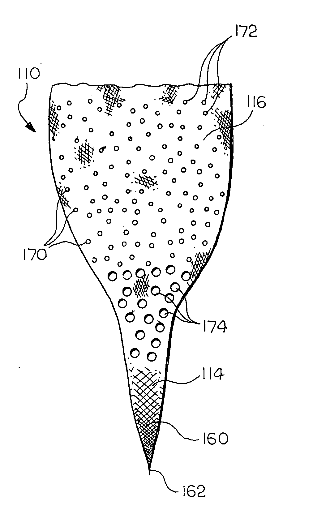
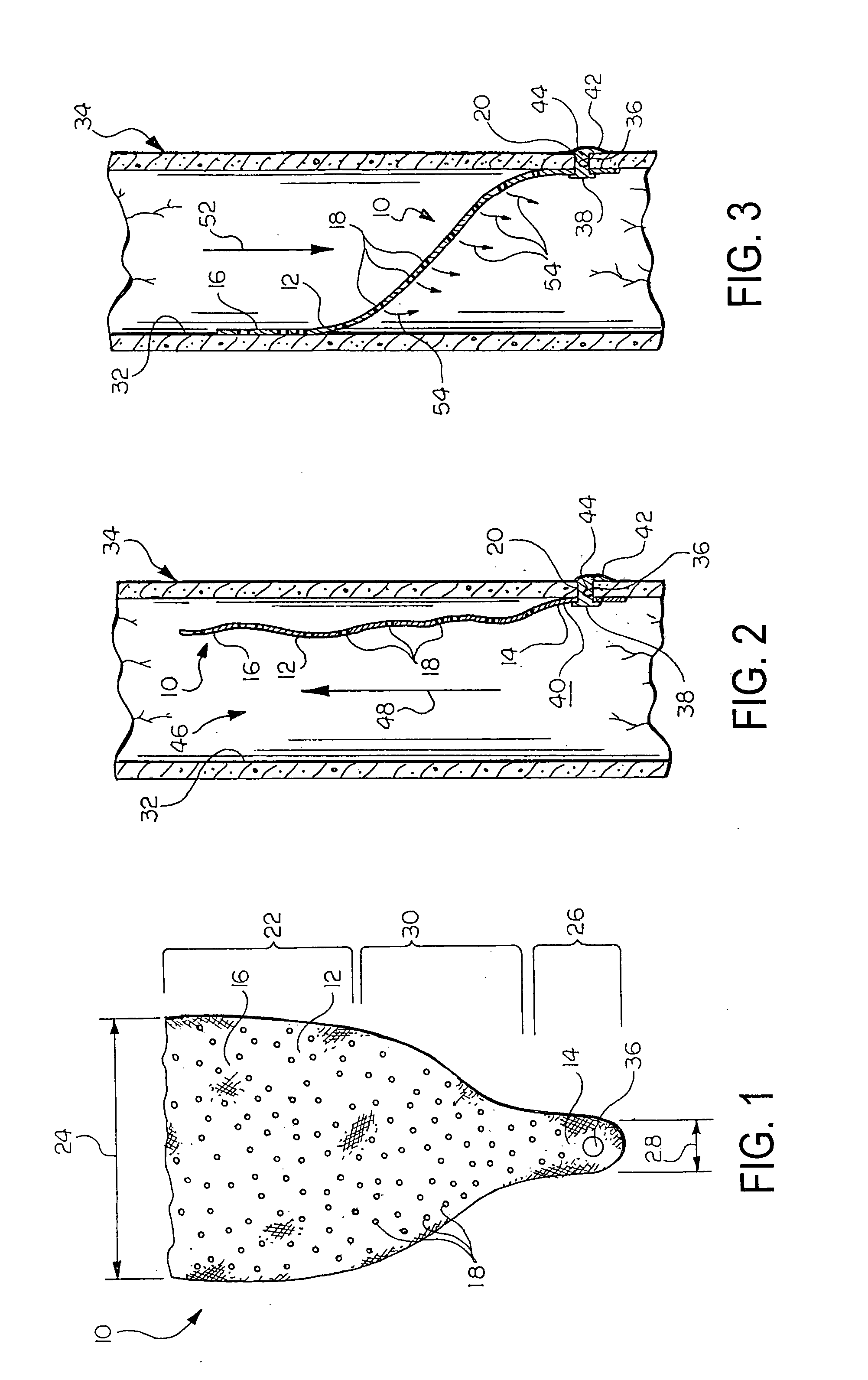
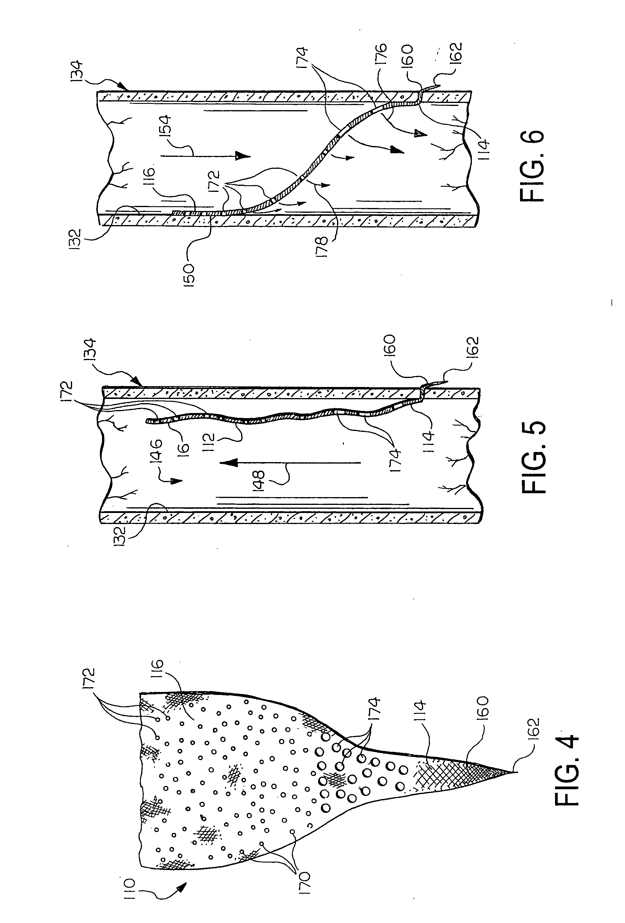
[0009] The present invention provides valves for implantation in body vessels and other suitable environments. In one exemplary embodiment, a valve comprises a leaflet that has a valve portion that is moveable between first and second positions. In the first position, the leaflet permits fluid flow in a first direction through a body vessel in which the valve is implanted. In the second position, the leaflet substantially prevents fluid flow through the body vessel in a second, opposite direction. The leaflet defines a plurality of pores, and the valve includes a means for maintaining an axial position of the leaflet in the body vessel in which the valve is implanted.
[0010] In another exemplary embodiment, a valve comprises a support frame having radially compressed and radially expanded configurations. The valve includes at least one leaflet attached to the support frame that defines a plurality of pores. At least a portion of the at least one leaflet is moveable between first and...
PUM
 Abstract
Description
Claims
Application Information