
Cord holder

a cord holder and clip technology, applied in the field of cord holders, can solve the problems of affecting the efficient delivery of services, affecting the service quality of users, and not fully addressing unique needs, so as to achieve the effect of quick disengagement of the cord holder and effective treatment of fatigu

Inactive Publication Date: 2006-03-23
SENINK CATHERINE M
View PDF12 Cites 31 Cited by
  • Summary
  • Abstract
  • Description
  • Claims
  • Application Information

AI Technical Summary

Benefits of technology

[0014] The present invention provides a light-weight device that enables quick disengagement of the cord holder. The cord retainer can remain attached to the cord, and numerous cord retainer can be left attached to the cords of the various tools that might be required over a given period of time. By securing the cord to the user's wrist in this way, fatigue can also be effectively addressed.

Problems solved by technology

The cords tend to be of sufficient weight and length that they may cause fatigue of the user's arm and hand with prolonged use, as well as often providing a physical obstruction, potentially hindering the efficient delivery of services.
While the prior art teaches means of addressing problems associated with the cords of power tools, these proposed solutions do not fully address the unique needs associated with smaller and more numerous tools as would be employed within a dental practice, where numerous devices may be used in rapid succession.
The prior art fails to provide a quickly removable device with the light-weight construction that is desirable in some contexts, nor does it address the arm or hand fatigue that may occur in this type of setting.

Method used


Image

  • Cord holder
  • Cord holder
  • Cord holder

Examples


Embodiment Construction

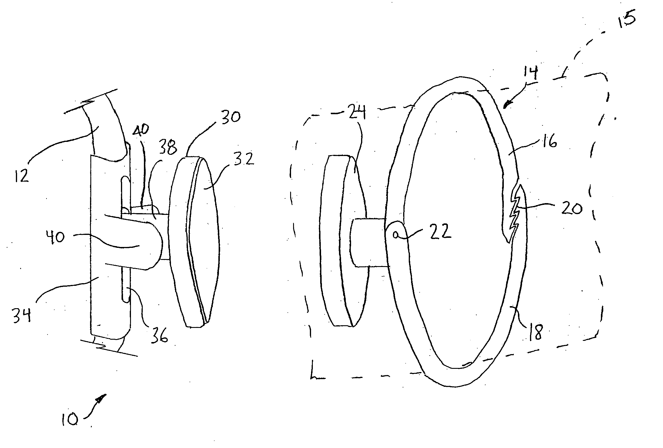
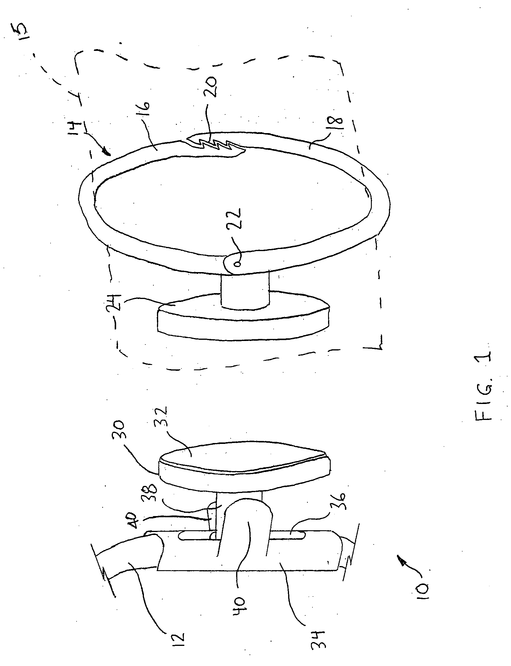
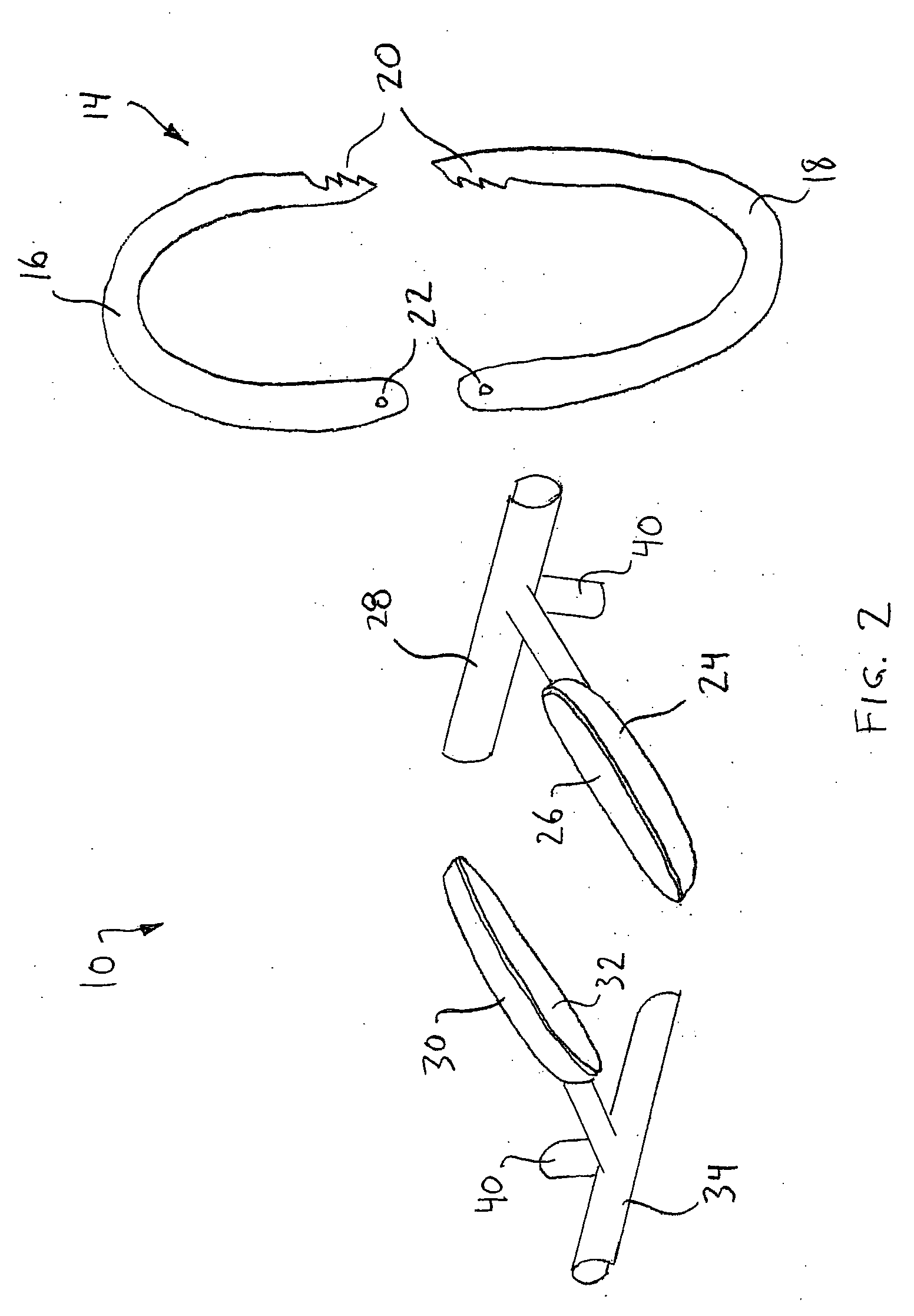
[0021] Referring to the accompanying drawings, and particularly to FIG. 1, there is illustrated a cord holder 10 according to the present invention. The cord holder 10 has a base member 14 for securing to an arm 15 of a user, a first fastener component 24 on the base member 14, a cord retainer 34 for removable attachment to the cord 12 of a power tool (not shown), and a second fastener component 30 on the cord retainer 34. In the illustrated exemplary embodiments, the first and second fastener components 24, 30 include magnetic pads 26, 32, respectively.

[0022] The base member 14, which roughly forms a bracelet in the illustrated exemplary embodiments, comprises first and second sections 16, 18 that are hingedly engaged to each other at one point at pivot 22, and engageable at an opposite point by means of ratchet teeth 20. As there are a series of teeth 20, the base member 14 can therefore be adjusted to comfortably fit different wrist sizes.

[0023] The second fastener component 30...


PUM


Abstract

A cord holder is provided for use with a hand-held tool having a power cord. The cord holder includes a two component releasable fastener, preferably magnetic. One component of the fastener is mounted on a bracelet to be worn by a user. The other component is mounted on a cord retainer to be fastened to the cord. The power cord can be supported on the user's wrist or arm by the cord holder retainer while the user holds and manipulates the tool.

Description

[0001] The present invention relates to the use of, hand-held power tools, and more particularly to devices for securing the power cords of the tools when in use. BACKGROUND OF THE INVENTION [0002] In certain environments, for example in dental practices, numerous small, hand-held tools (polishers, drills, and cavitrons being examples) are employed that use long electrical cords to supply the necessary power. The cords tend to be of sufficient weight and length that they may cause fatigue of the user's arm and hand with prolonged use, as well as often providing a physical obstruction, potentially hindering the efficient delivery of services. [0003] Prior attempts have been made to address the perceived need for tool cord supports. U.S. Pat. No. 3,155,298 to Brown discloses a supporting clip for use with the electric hair clippers cords, wherein the clip engages a user's breast pocket and serves as a hanger for a loop of the cord. U.S. Pat. No. 3,809,349 to Baedke teaches an elastic ...

Claims


Application Information

Patent Timeline
IPC IPC(8): F16G11/00A44B99/00
CPCA45F2005/008B65H75/4402Y10T24/3936H02G11/00F16G11/00F16G11/10F16G11/101
Inventor SENINK, CATHERINE M.
Owner SENINK CATHERINE M
Learn More