Slide wiring apparatus

Active Publication Date: 2006-03-23
YAZAKI CORP +1
View PDF1 Cites 20 Cited by
  • Summary
  • Abstract
  • Description
  • Claims
  • Application Information

AI Technical Summary

Benefits of technology

[0034] In the invention of claim 5, a foreign matter, intruding into the interior of the casing portion through the slit, interferes with the second projecting portion, and is positively kept away from the slider. This positively prevents a situation in which the foreign matter, intruding into the interior of the casing portion, prevents the movement of the slider.
[0035] In the invention of claim 6, the distance D between the rail and the inner surface of the casing portion is smaller than the outer diameter of the wire, and therefore the wire is positively prevented from moving between the wire moving space and the wire accommodating space. Therefore, the wire is prevented from catching the slider or other.
[0036] In the invention of claim 7, the superposing portions of the lower casing and upper casing divide the wire accommodating space into the first space and the second space. Therefore, the wire within the wire accommodating space is prevented from being displaced in the direction of the width of the rail to move between the first space and the second space. Therefore, the wire is prevented from being entangled within the wire accommodating space, thereby positively preventing the wire from being damaged.
[0037] In the invention of claim 8, the sp

Problems solved by technology

Therefore, in the slide wiring apparatus, when the seat and hence the protector are repeatedly moved, the

Method used


Image

  • Slide wiring apparatus
  • Slide wiring apparatus
  • Slide wiring apparatus

Examples


Embodiment Construction

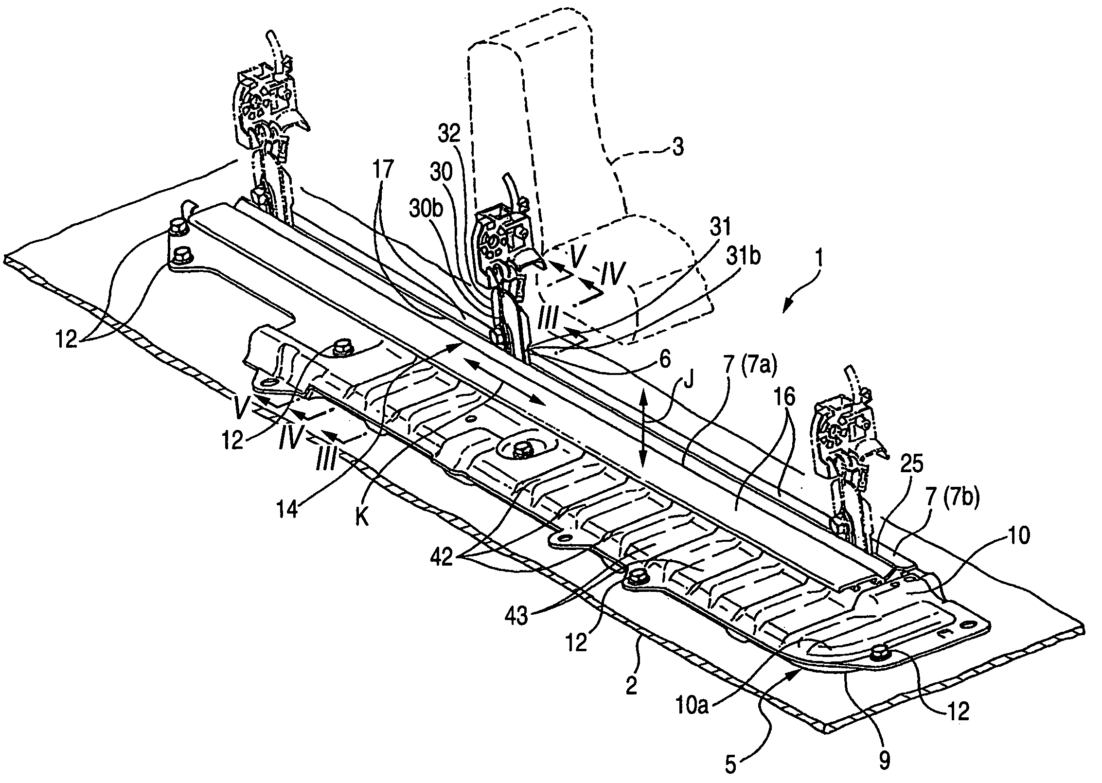
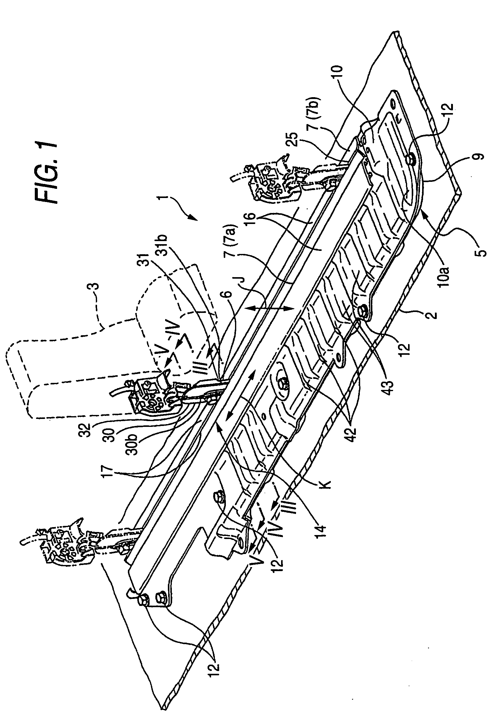
[0058] One preferred embodiment of a slide wiring apparatus 1 of the present invention will now be described with reference to FIGS. 1 to 11. As shown in FIG. 1, the slide wiring apparatus 1 (hereinafter referred to merely as “wiring apparatus”) is designed to install wires 13 (shown in FIGS. 9 and 10) over a region including a floor 2 (serving as a vehicle body of an automobile) of a passenger room and a seat 3 (serving as a slide member) mounted on the floor 2 for sliding movement in a direction of arrow K

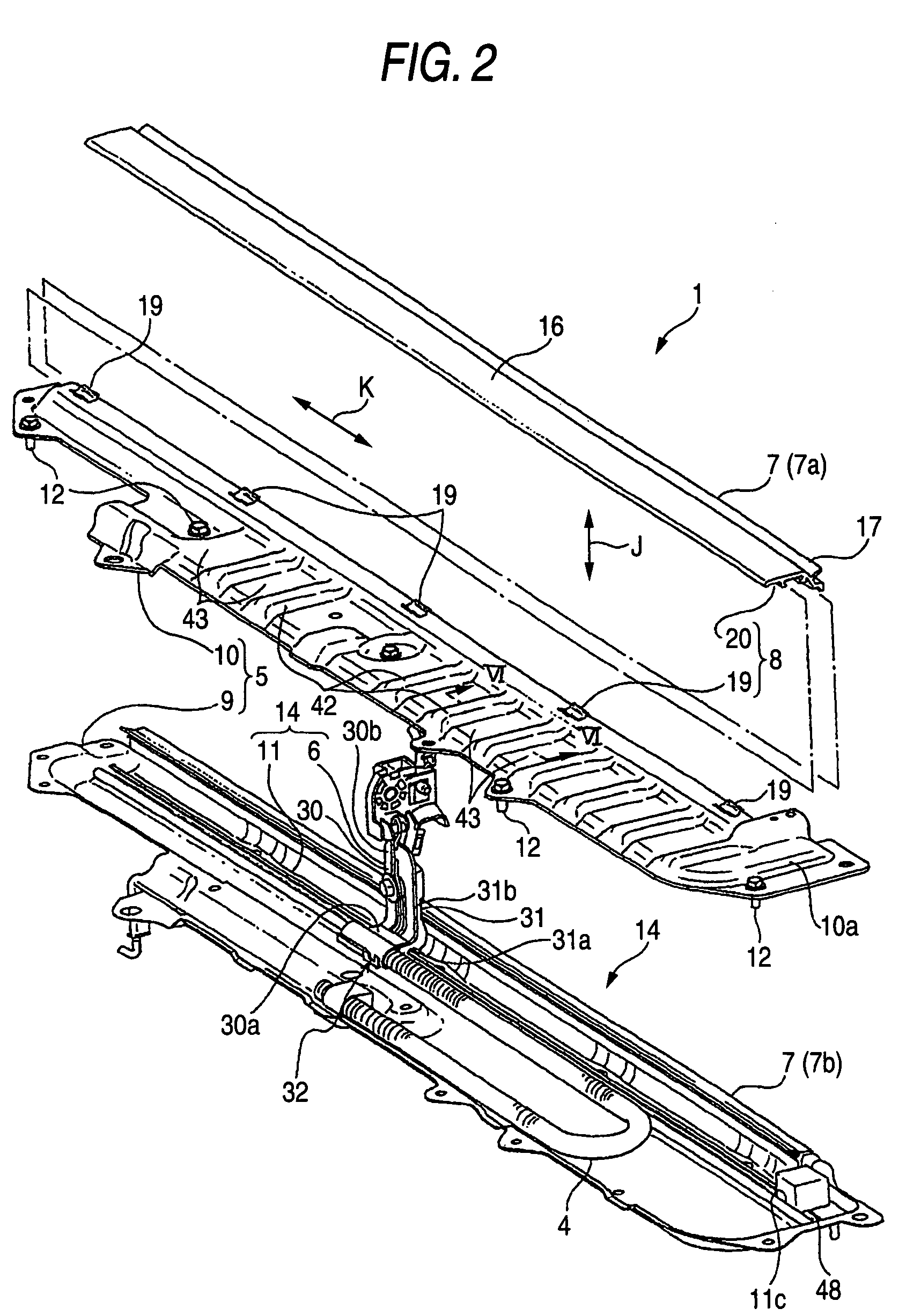
[0059] Each of the wires 13 is a so-called sheathed wire comprising an electrical conductor, and an insulating sheath. The plurality of wires 13 are bundled together, and are passed through a corrugated tube 4 (shown in FIG. 2). The corrugated tube 4 is made of a synthetic resin such for example as PP (polypropylene), and is formed into a tubular shape. The corrugated tube 4 is also formed into a bellows-shape. The plurality of wires 13 are passed through the corrugated tube 4, ...


PUM


Abstract

A slide wiring apparatus is provided with a linearly-moving device. The linearly-moving device includes a casing portion, a rail and a protector. The casing portion is mounted on a floor serving as a vehicle body. The rail is accommodated within the casing portion, and is mounted on this casing portion. The protector is supported on the rail so as to move in a longitudinal direction thereof. The protector receives wires. A space within the casing portion is divided by the rail into a wire moving space and a wire accommodating space.

Description

BACKGROUND OF THE INVENTION [0001] 1. Field of the Invention [0002] This invention relates to a slide wiring apparatus for installing wires over a region including, for example, a vehicle body (such as a floor of an automobile) and a slide member (such as a seat) slidably mounted on the vehicle body. [0003] 2. Related Art [0004] An automobile (moving body) is equipped with seats (slide bodies) slidable relative to a floor (vehicle body) of a passenger room. For example, a seat sensor for detecting or checking whether or not the passenger is seated is provided at the seat. Therefore, automobiles, equipped with slidable seats, have heretofore been provided with various slide wiring apparatuses. [0005] Such a slide wiring apparatus comprises a casing portion, a rail, a protector (serving as a slider), and a cable (or wires) The casing portion is mounted on the floor. The rail is formed into a linear shape, and is accommodated within the casing portion, and is mounted on this casing por...

Claims


Application Information

Patent Timeline
IPC IPC(8): H02G3/04
CPCB60N2/06B60N2002/0264H02G11/00B60N2/0264
Inventor GOTO, HIROKITERADA, TOMOYASUYOSHIMURA, KATSUYAMURAOKA, TADASHIWAKAMATSU, HIROYUKIWADA, HIROFUMI
Owner YAZAKI CORP
Why Eureka
Try Eureka