Rear suspension of a two-wheel vehicle or the like

a two-wheel vehicle and rear suspension technology, applied in the direction of motorcycling, bicycles, unicycling, etc., can solve the problems cyclical compression of the suspension, and the rear suspension thus having the drawback of dissipating some of the drive torque provided, so as to eliminate the kick-back effect

Inactive Publication Date: 2006-03-23
CYCLES LAPIERRE
View PDF11 Cites 45 Cited by
  • Summary
  • Abstract
  • Description
  • Claims
  • Application Information

AI Technical Summary

Benefits of technology

[0017] Thus, the instantaneous centre of rotation that is initially located on the upper strand of the transmission chain or on the straight line extending it is displaced upwards along a curved path oriented towards the rear hub of the swinging arm until it follows a globally horizontal rectilinear path, which eliminates the kick-back effect that is particularly unpleasant for the cyclist.

Problems solved by technology

When there is an energetic kick on the pedals, such as a kick on the pedal in order to move the bike off or when the cyclist stands out of the saddle, on the pedals, this type of rear suspension generates a “pumping” effect resulting in a cyclical compression of the suspension, even on a perfectly level surface.
This type of rear suspension thus has the drawback of dissipating some of the drive torque provided by the cyclist in the shock absorber instead of contributing to driving the bike along.
Such a rear suspension also has the drawback of generating a “pumping” effect resulting in a cyclical compression of the suspension even on a perfectly level surface, thus dissipating some of the drive torque provided by the cyclist in the shock absorber instead of contributing to driving the bike along.
This rear suspension also has the drawback of generating a particularly detrimental “pumping” effect.
All these devices, although generating an anti-pumping effect, have the drawback of resulting in a lengthening of the chain strand when the swinging arm is displaced upwards, which gives rise to a variation in chain tension that generates a kick-back effect that counteracts rotation of the pedals and bottom bracket bearing assembly.
This kick-back effect gives rise to a disagreeable, jolting sensation for the cyclist.
This type of bike rear suspension has the drawback, although it limits the kick-back effect, of not generating an anti-pumping effect, the instantaneous centre of rotation being displaced globally forwards and downwards when the swinging arm is displaced upwards.

Method used


Image

  • Rear suspension of a two-wheel vehicle or the like
  • Rear suspension of a two-wheel vehicle or the like
  • Rear suspension of a two-wheel vehicle or the like

Examples


Embodiment Construction

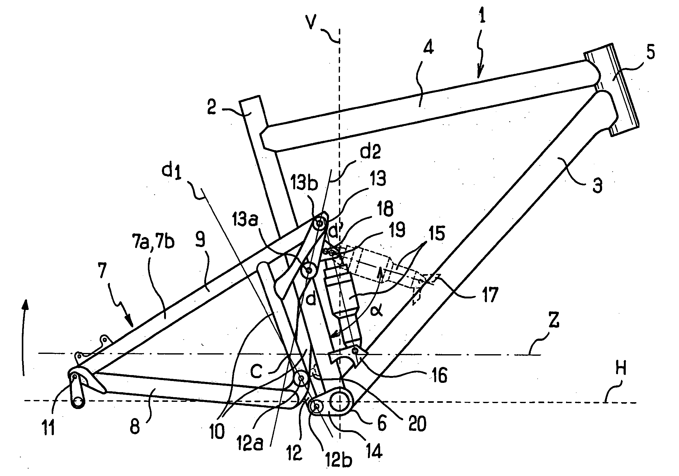
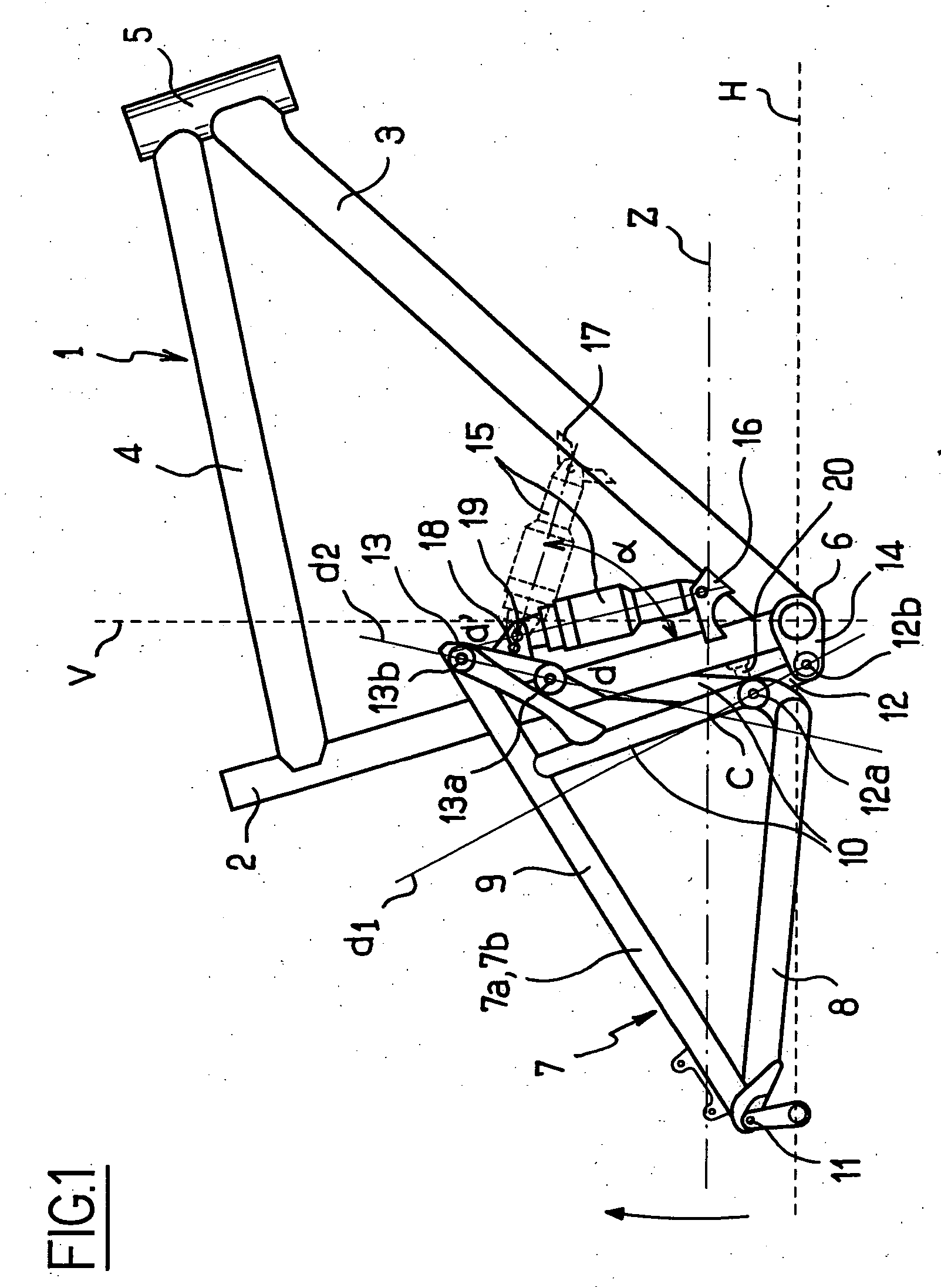
[0023] A description will be given below by way of non-limiting example of a rear suspension of a bicycle of the mountain-bike (MTB) type. However, the rear suspension according to the invention could be adapted to any other vehicle without thereby departing from the scope of the invention.

[0024] With reference to FIGS. 1 and 2, the MTB comprises a frame known as a triangulate frame consisting of a globally vertical seat tube 2, a down tube 3 welded to the lower end of the seat tube 2, a horizontal tube 4 assembled at the lower end of the seat tube 2 and a globally vertical fork tube 5, the down tube 3 being furthermore secured to said fork tube 5, also by means, of welding. Although this is not shown in FIG. 1, said fork tube 5 carries forks that comprise a suspension, preferably of the telescopic type, carrying, at its lower end, the axle of the hub of the front wheel. Quite obviously, handlebars are conventionally secured to the upper end of the forks, for steering the MTB. Furt...


PUM


Abstract

The present invention relates to a rear suspension for a vehicle such as a bicycle, a motorcycle or the like, of the type that includes a frame (1), a swinging arm (7) integral with the frame (1) carrying the axle (11) of the hub of a drive wheel and a shock absorber (15) whose ends are secured, respectively, to the frame (1) and to the swinging arm (7), the drive torque being transmitted to the drive wheel by a chain (Z) extending between a drive sprocket secured to the frame (1) and a driven sprocket secured to the axle (11) of the hub of the drive wheel, said chain (Z) between the drive and driven sprockets forming two strands; the stretched, upper one, which transmits the drive torque to the rear drive wheel, and the other, “return” lower one, the swinging arm (7) being secured to said frame (1) by at least two articulation means (12, 13) so that the swinging arm (7) pivots about an “instantaneous centre of rotation” point C that is movable when the hub of the drive wheel is displaced on either side of its reference position Pr corresponding to the position of the axle (11) of the hub of the drive wheel when the vehicle is in a static equilibrium position, characterized in that the instantaneous centre of rotation C is displaced upwards along a parabolic path T, the asymptote A of which is oriented towards the rear free end of the swinging arm (7) carrying the axle (11) of the hub of the drive wheel when said hub of the drive wheel is displaced above its reference position Pr.

Description

FIELD OF THE INVENTION [0001] The present invention relates to an improvement to a rear suspension of a vehicle such as a bicycle, a motorcycle or the like, of the type that includes a frame, a swinging arm integral with the frame and carrying the axle of the hub of a rear drive wheel and a shock absorber whose ends are secured, respectively, to the frame and to the swinging arm, said suspension generating an “anti-pumping” effect. BACKGROUND OF THE INVENTION [0002] Mountain bikes—“MTBs”—whose rear suspension consists of a swinging arm articulated at the bottom part of the seat tube and interacting with a shock absorber are well known. Said swinging arm pivots about a fixed rod parallel to the axle of the drive sprocket carried by the bottom bracket positioned at the lower end of the frame, i.e. at the intersection of the down tube and the seat tube of the frame. Furthermore, the ends of the shock absorber are secured to the swinging arm and, respectively, to the horizontal tube con...

Claims


Application Information

Patent Timeline
Patent Type & Authority Applications(United States)
IPC IPC(8): B62K5/00
CPCB62K25/286
Inventor LESAGE, PHILIPPEANTONOT, EMMANUEL
Owner CYCLES LAPIERRE
Why Eureka
Try Eureka