System and method for burn-in test control

a technology of system and method, applied in the field of electronic circuit testing, can solve problems such as component failure, component failure, and component failure, and achieve the effects of reducing the number of components, and reducing the probability of failur

Inactive Publication Date: 2006-03-23
KK TOSHIBA
View PDF6 Cites 16 Cited by
  • Summary
  • Abstract
  • Description
  • Claims
  • Application Information

AI Technical Summary

Benefits of technology

[0012] The LBIST controller is configured to receive device temperature information from the thermal sensor and to modify control signals that are provided to the LBIST circuitry in order to cause the LBIST circuitry to operate in a manner that drives the device temperature to a desired level. In one embodiment, the LBIST controller adjusts the speed with which the LBIST circuitry scans data into and out of a plurality of scan chains, thereby adjusting the amount of heat generated by this operation, which in turn affects the temperature of the device.

Problems solved by technology

Each of the individual components that make up the device has an associated likelihood that the component will fail.
If one of the components fails, the functions performed by component will no longer be performed, so the device fails as well.
The failure rates for electronic devices normally change over time.
For a typical device, the failure rate will initially be relatively high.
This high initial failure rate is due to components that are defective and therefore prone to failure.
For those devices that do not have any components that are defective and therefore likely to fail in this initial interval, the failure rate will drop from the relatively high initial levels to much lower levels, and will remain at these lower levels for a relatively long period of time.
At some point, the failure rates will increase again as the components began to wear out.
At this point, the devices have reached the ends of their useful lives, and the failures are the result of “old age,” rather than defective components.
This causes defective products to fail at the manufacturer's facility during testing, rather than in a customer's possession during normal operation by the customer.
The control of the test conditions as desirable because, while it is useful to subject the devices to the harshest conditions that may be encountered during normal use, it is counterproductive to make the conditions more harsh than could be expected, as this could cause the failure of products that would not have failed during normal use.
For instance, in the case of electronic devices such as microprocessors or other large-scale integrated circuits, it is not unusual to test the devices using expensive test machines that are capable of individually controlling the test conditions for many different devices at the same time.
It is easy to understand that, because of their complexity, these test machines are typically very expensive to purchase and very expensive to operate.

Method used


Image

  • System and method for burn-in test control
  • System and method for burn-in test control
  • System and method for burn-in test control

Examples


Embodiment Construction

[0026] One or more embodiments of the invention are described below. It should be noted that these and any other embodiments described below are exemplary and are intended to be illustrative of the invention rather than limiting.

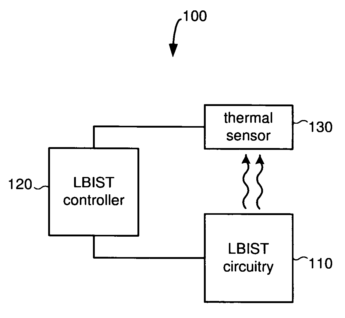
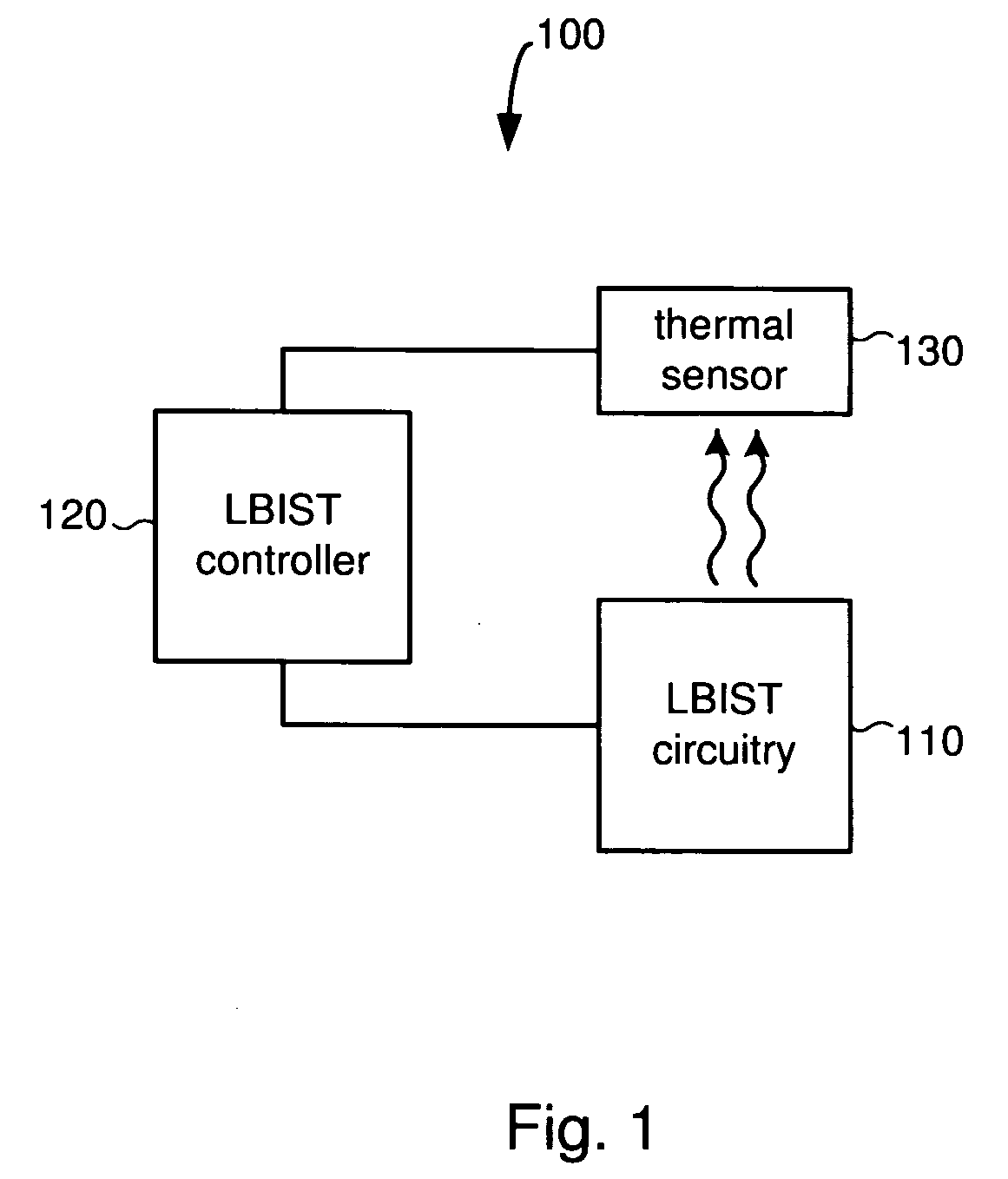
[0027] Broadly speaking, the invention includes systems and methods for controlling test conditions using logic built-in self-test (LBIST) components to affect test conditions. In one embodiment, an LBIST controller is coupled to LBIST circuitry that is incorporated into the design of a device under test, and also to a thermal sensor that is in thermal communication with the device under test. The LBIST controller is configured to receive device temperature information from the thermal sensor and to modify control signals that are provided to the LBIST circuitry in order to cause the LBIST circuitry to operate in a manner that drives the device temperature to a desired level.

[0028] In one embodiment, the LBIST circuitry that is incorporated into the device...


PUM


Abstract

Systems and methods for controlling test conditions using logic built-in self-test (LBIST) components to affect test conditions. In one embodiment, an LBIST controller is coupled to LBIST circuitry that is incorporated into the design of a device under test, and also to a thermal sensor that is in thermal communication with the device under test. The LBIST controller is configured to receive device temperature information from the thermal sensor and to modify control signals that are provided to the LBIST circuitry in order to cause the LBIST circuitry to operate in a manner that drives the device temperature to a desired level. In one embodiment, the LBIST controller adjusts the speed with which the LBIST circuitry scans data into and out of a plurality of scan chains, thereby adjusting the amount of heat generated by this operation, which in turn affects the temperature of the device.

Description

BACKGROUND [0001] 1. Field of the Invention [0002] The invention relates generally to the testing of electronic circuits, and more particularly to systems and methods for controlling test conditions using available logic built-in self-test (LBIST) components to affect the test conditions. [0003] 2. Related art [0004] Electronic devices consist of many individual components that are interconnected in such a way as to provide the functionality of the device. Each of the individual components that make up the device has an associated likelihood that the component will fail. If one of the components fails, the functions performed by component will no longer be performed, so the device fails as well. [0005] The failure rates for electronic devices normally change over time. For a typical device, the failure rate will initially be relatively high. This high initial failure rate is due to components that are defective and therefore prone to failure. For those devices that do not have any c...

Claims


Application Information

Patent Timeline
Patent Type & Authority Applications(United States)
IPC IPC(8): G06F19/00
CPCG01R31/318555G01R31/2855
Inventor KIRYU, NAOKI
Owner KK TOSHIBA
Why Eureka
Try Eureka