Hose clamp

Inactive Publication Date: 2006-03-30
CHEN DIAN TAI
View PDF8 Cites 11 Cited by
  • Summary
  • Abstract
  • Description
  • Claims
  • Application Information

AI Technical Summary

Benefits of technology

[0007] The present invention has been accomplished under the circumstances in view. It is the main ob

Problems solved by technology

This design of hose clamp is still not satisfacto

Method used


Image

  • Hose clamp
  • Hose clamp
  • Hose clamp

Examples


Example

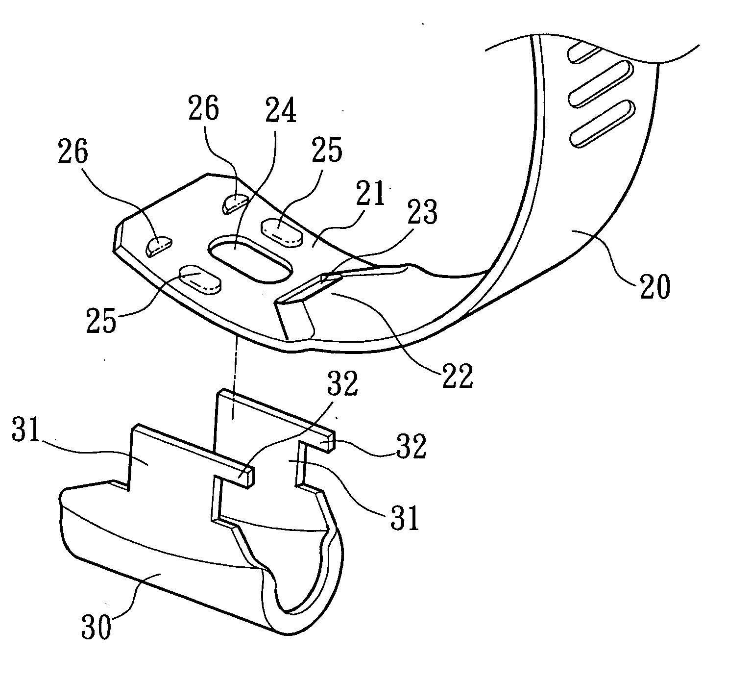
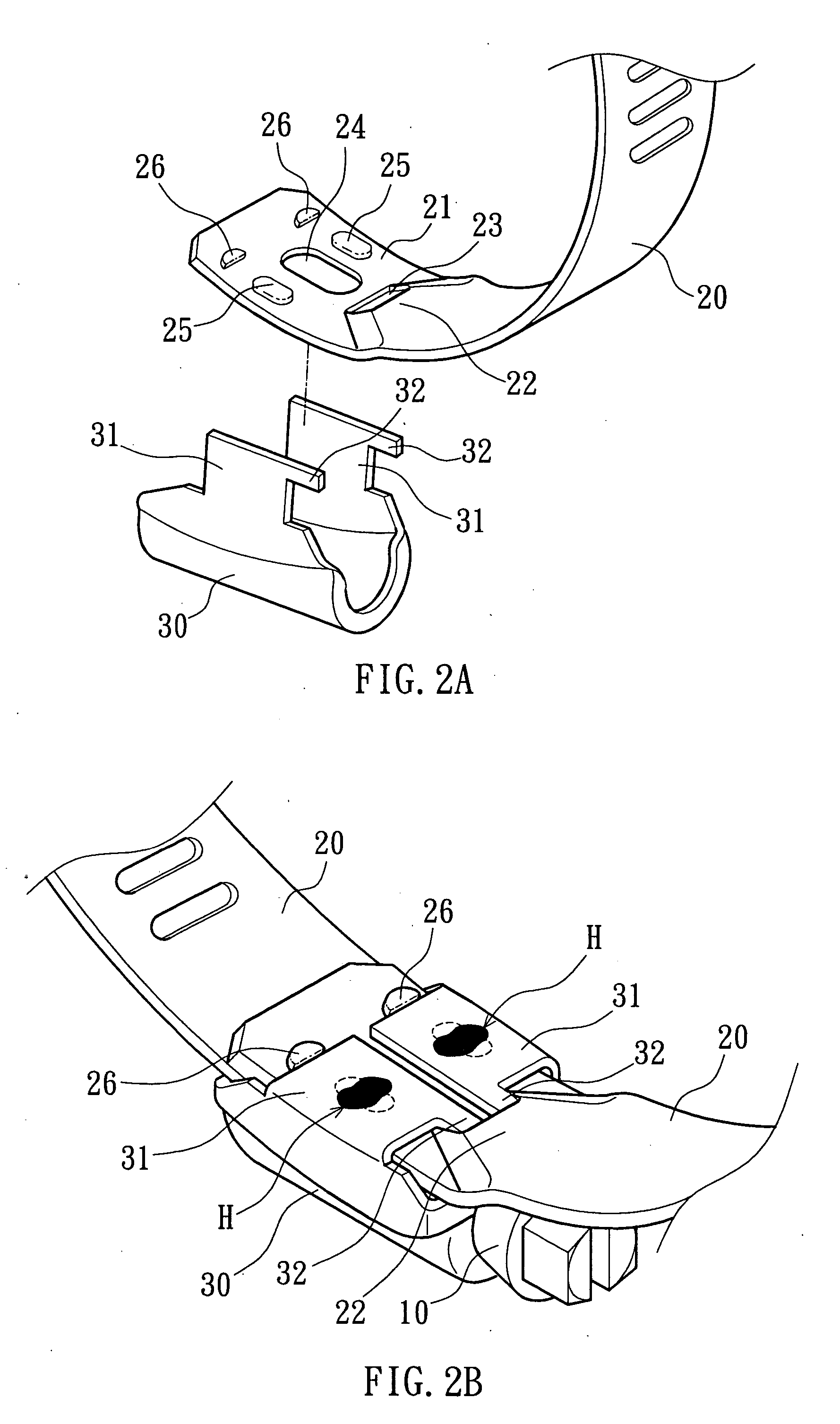
[0020] Referring to FIGS. 2A, 2B, and 3, a hose clamp in accordance with one embodiment of the present invention is shown comprised of a binding belt 20 and a screw holder 30 mounted with a screw 10.

[0021] The binding belt 20 has a flat head 21, a protruded portion 22 adjacent to the flat head 21, a locating hole 23 formed in the protruded portion 22, a through hole 24 cut through the top and bottom surfaces of the flat head 21, two welding flanges 25 protruded from the bottom surface of the flat head 21 at two opposite lateral sides of the through hole 24, and two stop blocks 26 protruded from the bottom surface of the flat head 21 in front of the through hole 24.

[0022] The screw holder 30 comprises two mounting plates 31 symmetrically disposed at two sides. Each mounting plate 31 has a positioning rod 32.

[0023] During installation, the screw holder 30 is attached to the top surface of the flat head 21 of the binding belt 20, and then the mounting plates 31 are respectively bent...


PUM


Abstract

A hose clamp includes a binding belt, which has a flat head, a protruded portion adjacent to the flat head, a locating hole formed in the protruded portion, a through hole cut through the flat head, two bottom welding flanges at two sides of the through hole, and two bottom stop blocks in front of the through hole, and a screw holder attached to the top surface of the flat head to hold a screw for joining the ends of the binding belt and having two mounting plates respectively clamped on the bottom surface of the flat head and stopped between the stop blocks and the protruded portion and respectively welded to the welding flanges by spot welding, the mounting plates each having a positioning rod respectively engaged into the locating hole in the protruded portion.

Description

BACKGROUND OF THE INVENTION [0001] 1. Field of the Invention [0002] The present invention relates to a hose clamp for fastening a hose to a pipe and more particularly, to a high-strength hose clamp, which is durable in use. [0003] 2. Description of the Related Art [0004]FIGS. 1A and 1B show a hose clamp according to the prior art. According to this design, the hose clamp comprises a binding belt 11, and a screw holder 15 holding a screw 10. The binding belt 11 has a through hole 14 in the flat head thereof, two side notches 13 at two opposite lateral sides of the flat head, and four stop flanges 12 at two ends of each of the side notches 13. The screw holder 15 has two mounting plates 16 respectively fastened to the side notches 13 and stopped between the stop flanges 12 and locating rods 17 respectively extended from the mounting plates 16 at two sides and inserted through the through hole 14 from the back side toward the front side and then respectively clamped on the front surfac...

Claims


Application Information

Patent Timeline
IPC IPC(8): F16L33/08
CPCY10T24/1427F16L33/08
Inventor CHEN, DIAN-TAI
Owner CHEN DIAN TAI
Why Eureka
Try Eureka