Rotary cutter

a rotary cutter and cutter body technology, applied in the field of rotary cutters, can solve the problems of high cost of upper knife blades, knife blade breakage, and poor cutting quality, and achieve the effect of convenient adjustment of cutting gaps and reducing costs

Inactive Publication Date: 2006-03-30
MULLER MARTINI HLDG
View PDF10 Cites 10 Cited by
  • Summary
  • Abstract
  • Description
  • Claims
  • Application Information

AI Technical Summary

Benefits of technology

[0009] It is an object of the present invention to provide a rotary

Problems solved by technology

For example, if the cutting gap is too wide, the cutting quality will be insufficient.
If the cutting gap is too narrow, the knife blades can break, especially the upper knife blade which is usually quite expensive.
Usually, such a contact between the knives is ca

Method used


Image

  • Rotary cutter
  • Rotary cutter
  • Rotary cutter

Examples


Embodiment Construction

[0022] Embodiments of the invention are discussed in detail below. In describing embodiments, specific terminology is employed for the sake of clarity. However, the invention is not intended to be limited to the specific terminology so selected. While specific exemplary embodiments are discussed, it should be understood that this is done for illustration purposes only. A person skilled in the relevant art will recognize that other components and configurations can be used without parting from the spirit and scope of the invention. All references cited herein are incorporated by reference as if each had been individually incorporated.

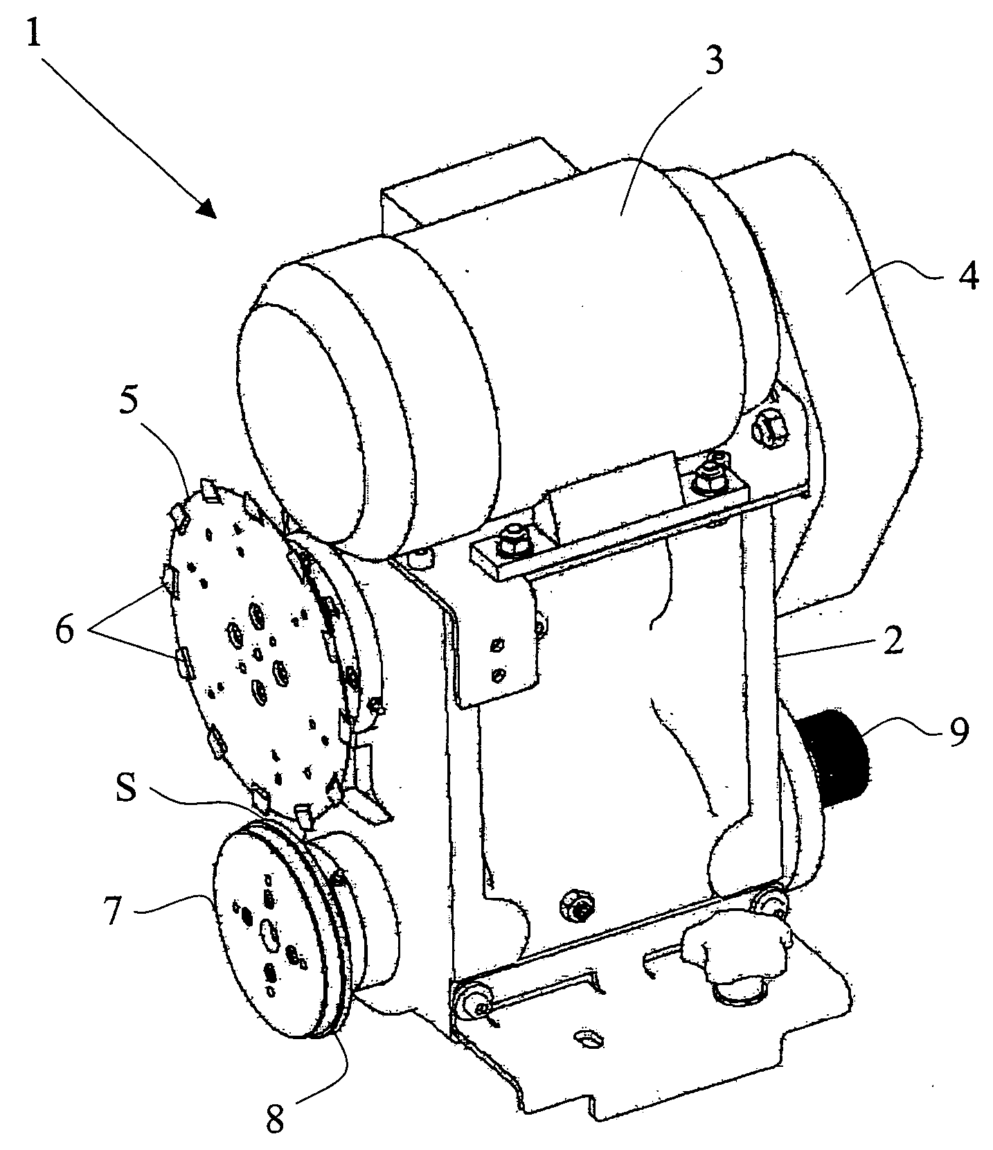
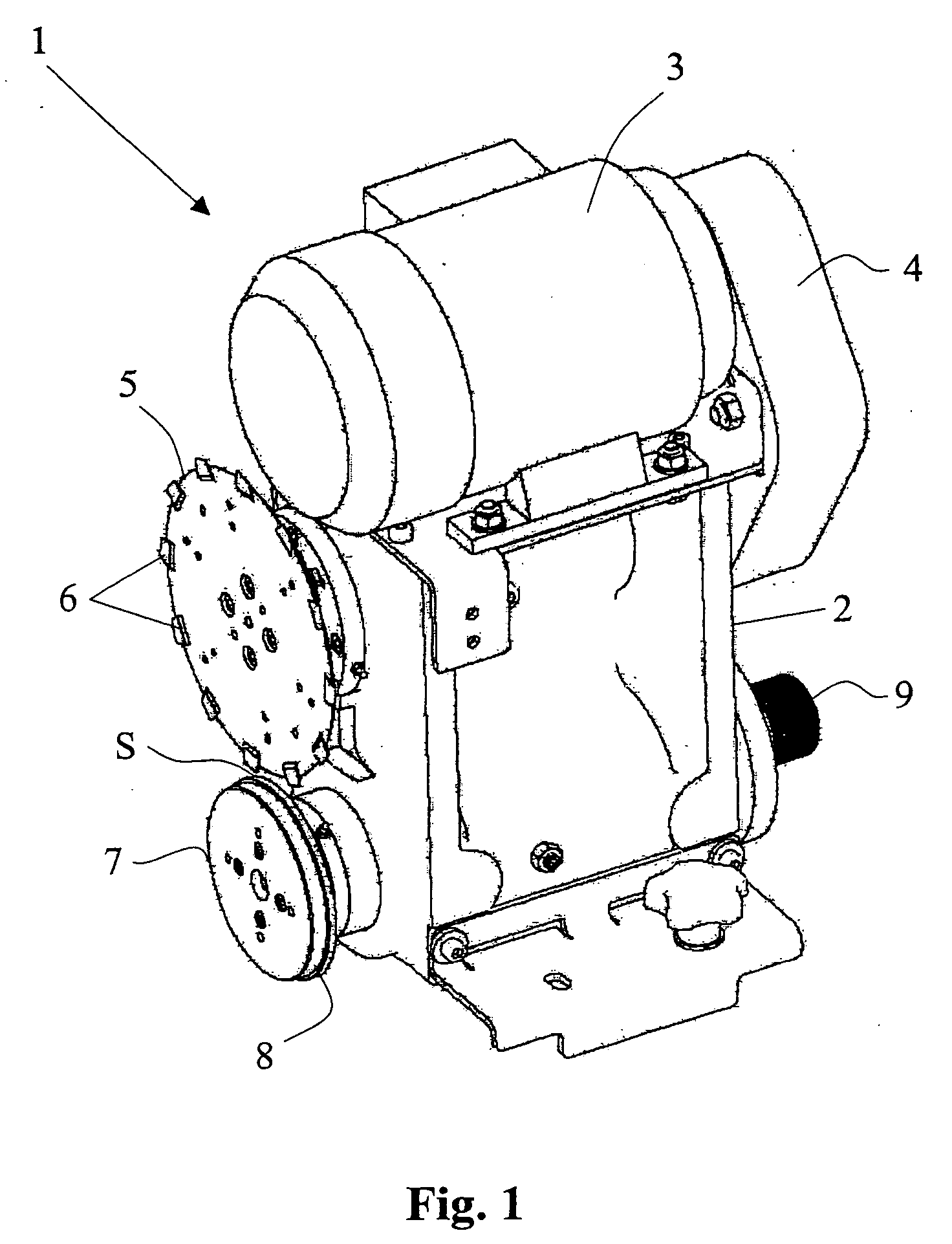
[0023] Referring to FIG. 1, an exemplary embodiment of a rotary cutter according to the present invention is shown. The rotary cutter 1 comprises a frame 2 having an upper knife 5 and lower knife 7 mounted thereto. The upper knife 5 can be driven via a motor 3, which is connected to a drive unit (located underneath a cover 4 and not visible in the embod...


PUM


Abstract

A rotary cutter comprises a first knife located on a knife shaft having a longitudinal axis, a second knife spaced from the first knife by an adjustable cutting gap, a control unit including a drive for turning at least one of the first knife or the second knife, and an adjusting mechanism for moving at least one of the first knife or the second knife in the direction of the longitudinal axis to adjust the cutting gap. The adjusting mechanism comprises a first signal transmitter for detecting a zero position of the first and second knives; a second signal transmitter for detecting the cutting position of the first and second knives; and an adjustment drive coupled to the first and second signal transmitters for movement of at least one of the first or second knives from the zero position to the cutting position.

Description

CROSS-REFERENCE TO RELATED APPLICATIONS [0001] This application claims the priority of European Patent Application No. 04405600.0-2302, filed on Sep. 20, 2004, the entire content of which is hereby incorporated herein by reference. BACKGROUND OF THE INVENTION [0002] 1. Technical Field [0003] The present invention relates generally to rotary cutters for the print-processing industry. More specifically, the present invention relates to rotary cutters including a pair of knives separated by an adjustable cutting gap. [0004] 2. Related Art [0005] Known rotary cutters typically include an upper knife and a lower knife, both of which are mounted on rotating shafts. The upper knife and lower knife are separated by a cutting gap that can be adjusted by an adjusting mechanism that allows one or both of the knives to be moved along the axis of its shaft. Typically, the cutting gap is adjusted manually by first moving one of the knives from a starting position to a zero position (i.e., where t...

Claims


Application Information

Patent Timeline
IPC IPC(8): B26D7/06B23D19/04B26D1/24B26D7/26
CPCB26D7/2635B26D5/02Y10T83/7843Y10T83/175Y10T83/659Y10T83/783Y10T83/7826
Inventor LIEBHEIT, STEFAN
Owner MULLER MARTINI HLDG
Why Eureka
Try Eureka