Electrically controlled actuating element on a machine

a technology of electric control and actuating element, which is applied in the direction of transmission systems, functional valve types, instruments, etc., can solve problems such as difficulties in all fields of application

Inactive Publication Date: 2006-02-09
TIEFENBACH CONTROL SYST
View PDF4 Cites 0 Cited by
  • Summary
  • Abstract
  • Description
  • Claims
  • Application Information

AI Technical Summary

Benefits of technology

[0008] It is an object of the invention to eliminate at least one of the described operating steps and to thus provide for a safer mounting of the

Problems solved by technology

This results for all fields of application in difficu

Method used


Image

  • Electrically controlled actuating element on a machine
  • Electrically controlled actuating element on a machine

Examples


Embodiment Construction

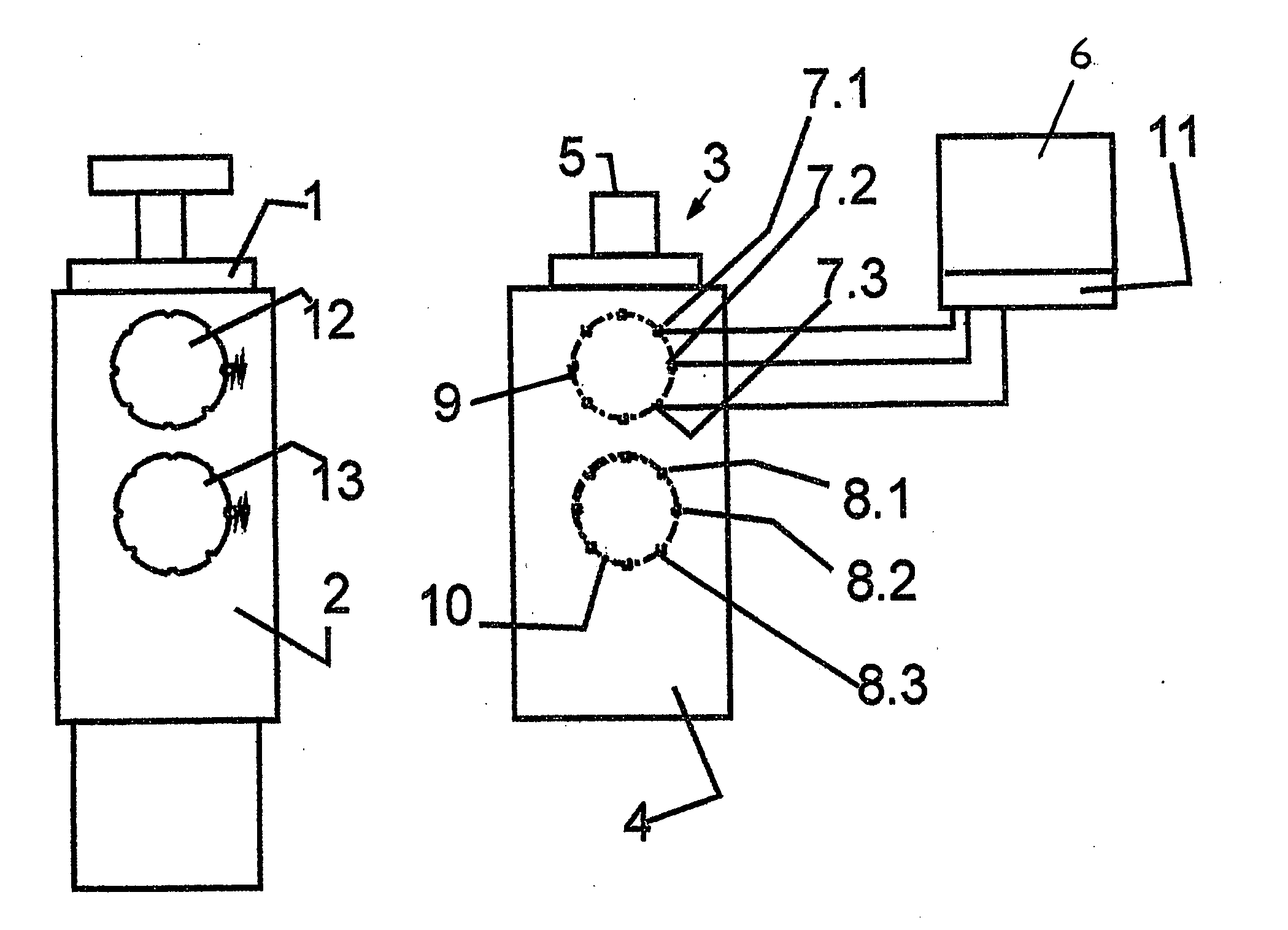
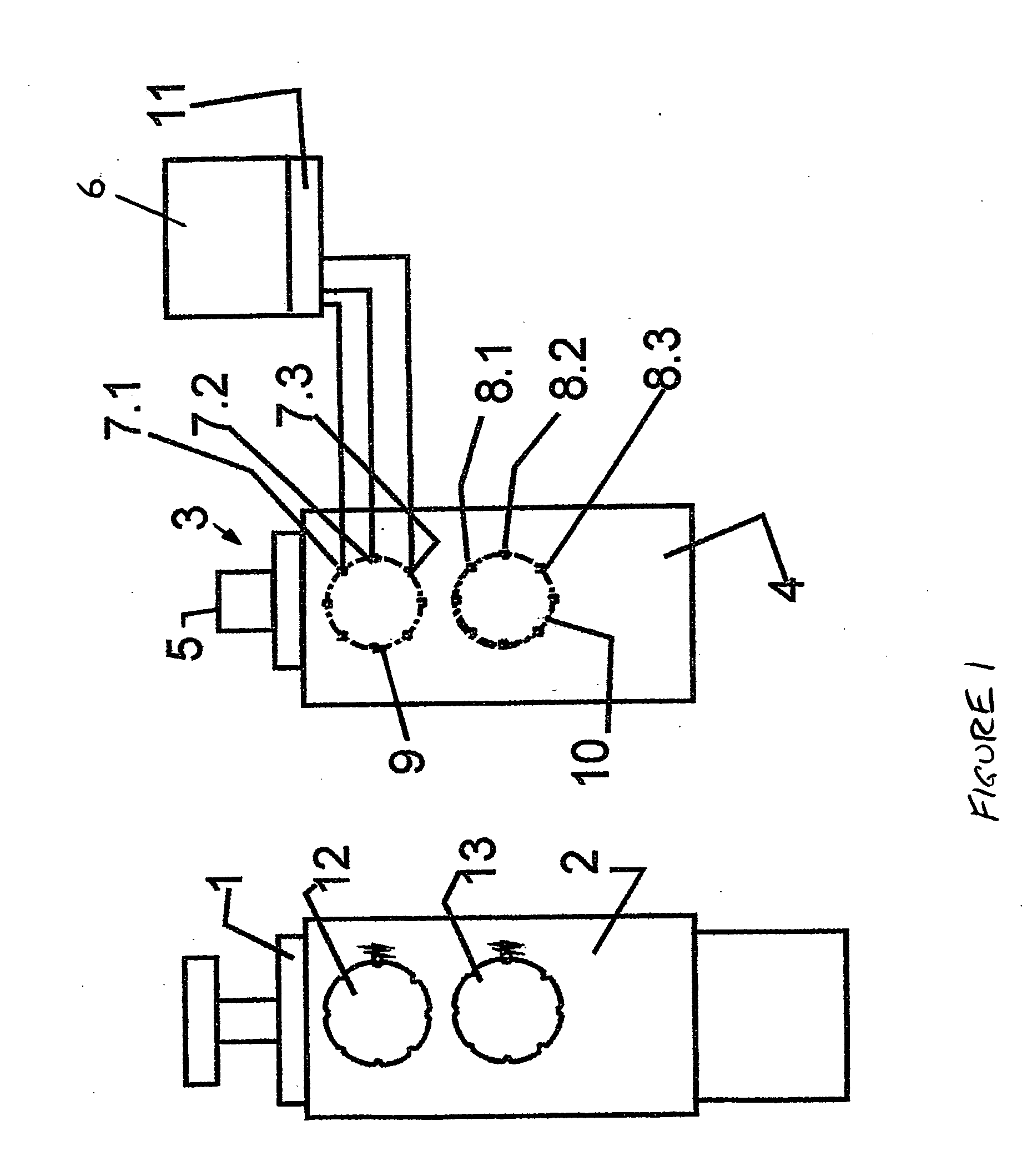
[0016] Illustrated as a machine is a cylinder-piston unit 1, which comprises a machine flange 2. The latter is adapted for receiving as actuating element a magnetically controlled, hydraulic valve 3 with a mounting flange 4. It should be noted that while both flanges are shown in the plane of the drawing, they overlie each other, when flanged together. A magnet 5 of the valve 3 is activated by a control subsystem 6 and the latter by a central control system not shown. Embedded in the mounting flange are switches 7.1-7.8 and 8.1-8.8, namely eight of each arranged respectively along one of the circles 9 and 10. The switches are positioned close to the connecting plane of the flange 4. Each of the switches 7 and 8 is arranged in an electric circuit that connects to the control subsystem. When one of the switches 7.1 et seq. and 8.1 et seq. is closed, the current of the corresponding circuit will be registered in the control subsystem. A memory 11 of the control subsystem stores all pos...


PUM


Abstract

An electrically controlled actuating element is arranged on a machine by a flange connection consisting of a mounting flange (4) and a machine flange (2), and is controlled by an electric control subsystem (6). Embedded in the mounting flange (4) in a predetermined geometric pattern is a plurality of electric switches (7.1-7.8, 8.1-8.8). Each switch is arranged in an electric circuit that connects to the control subsystem. In the machine flange (2), closing elements are arranged in some marking points of the geometric pattern in a geometric arrangement that is characteristic of the respective machine and associated to it. In an existing flange connection, the switches located in the respective marking points can be actuated by the closing elements. The control subsystem (6) of each consumer is provided with a memory (11), which stores the geometric arrangement of the closing elements that is characteristic of and associated to the machine.

Description

CROSS REFERENCE TO RELATED APPLICATION [0001] The present application is a continuation of international application PCT / DE2004 / 000676, filed 1 Apr. 2004, and which designates the U.S. The disclosure of the referenced application is incorporated herein by reference.BACKGROUND OF THE INVENTION [0002] The invention relates to an electrically controlled actuating element on a machine. [0003] Actuating elements of this type include, for example, hydraulic, electrohydraulic, or pneumatic valves, electromagnets, or actuators. Machines that are actuated by valves include, for example, cylinder-piston units or motors. [0004] A control subsystem is considered, for example, a subordinate control system of a central control system, which is associated to the machine, in particular a magnetic control in the case of magnetically actuated valves. [0005] Actuating elements of this type are often used in larger numbers for purposes of activating a corresponding number of machines. For example, in l...

Claims


Application Information

Patent Timeline
IPC IPC(8): F16K17/40F15B13/00F15B13/08F15B21/08
CPCF15B13/0853F15B13/0857F15B2013/006F15B21/085F15B13/0889Y10T137/1669
Inventor KUSSEL, WILLI
Owner TIEFENBACH CONTROL SYST
Why Eureka
Try Eureka