Fuel injection apparatus

a fuel injection and apparatus technology, applied in the direction of fuel injection apparatus, machine/engine, charge feed system, etc., can solve the problems of slow recovery of control chamber pressure at the end of injection, least insufficient control accuracy, etc., to minimise fuel pressure differential and reduce fuel pressure differential

Inactive Publication Date: 2006-03-30
DELPHI TECH INC
View PDF4 Cites 3 Cited by
  • Summary
  • Abstract
  • Description
  • Claims
  • Application Information

AI Technical Summary

Benefits of technology

[0020] In an alternative embodiment, the actuation means is arranged to vary the length of the second path length in response to the one or more injection parameters, thereby to minimise a fuel pressure differential between fuel within the injector control chamber and fuel within the injector delivery chamber at the time at which the injector control valve is actuated to move into the closed position.
[0021] It is also feasible for the actuation means to include first and second actuators, a first actuator for varying the length of the first path length in response to one or more injection parameters, and a second actuator for varying the length of the second path length in response to one or more injection parameters, thereby to minimise a fuel pressure differential between the control chamber and the delivery chamber.

Problems solved by technology

In known systems, it can be a disadvantage that recovery of control chamber pressure at the end of injection is too slow, or at least cannot be controlled with sufficient accuracy.

Method used


Image

  • Fuel injection apparatus
  • Fuel injection apparatus
  • Fuel injection apparatus

Examples


Embodiment Construction

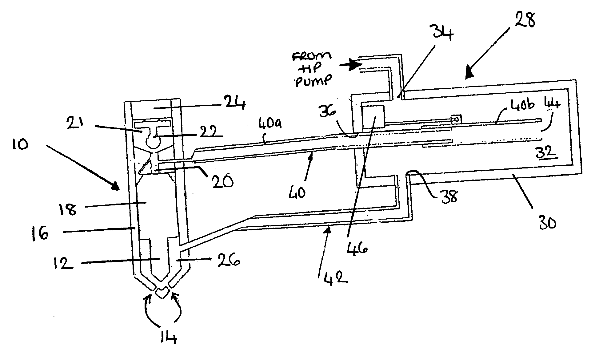
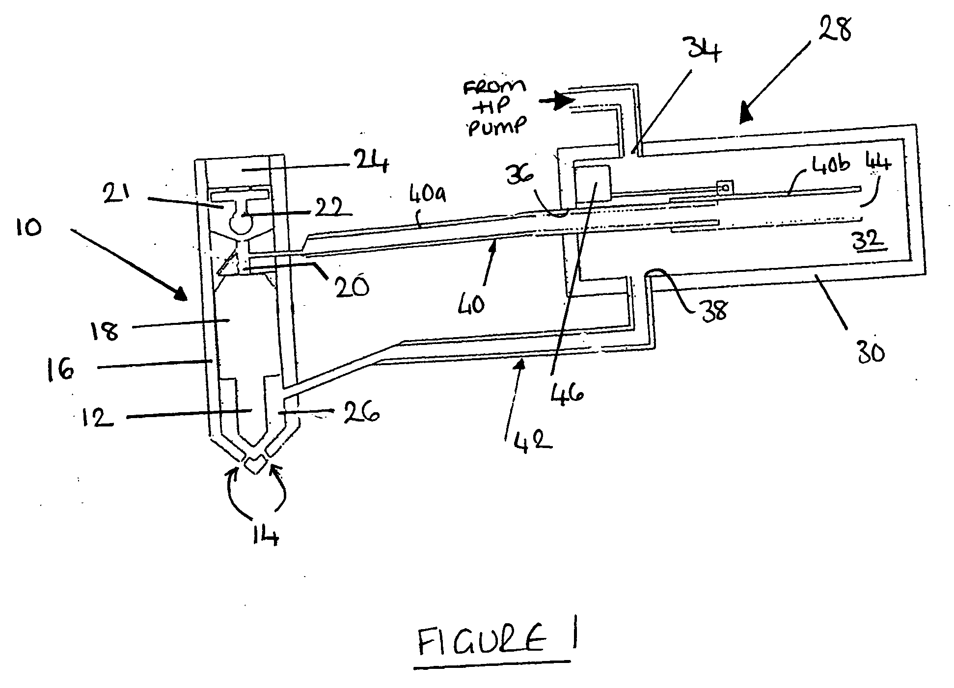
[0031] Referring to FIG. 1, a fuel injection apparatus of the present invention includes a fuel injector 10 having a valve member 12, or valve needle, which is engageable with a valve needle seating (not identified) to control fuel delivery through a plurality of injector outlets 14 provided in an injector body 16 within which the valve needle 12 moves. Two injector outlets 14 are shown in FIG. 1, although in practice any number of injector outlets may be provided.

[0032] The valve needle 12 of the injector 10 includes a seating end, which engages with the valve needle seating to control injection through the injector outlets 14, and an upper end 18 remote from the seating end. The upper end 18 of the valve needle 12 has an end surface exposed to fuel pressure within an injector control chamber 20 which is arranged to receive fuel at high pressure. An injector control valve 22 is operable between open and closed positions so as to control fuel pressure within the control chamber 20 ...


PUM


Abstract

A fuel injection apparatus for use in an internal combustion engine includes a fuel injector having a valve member which is operable to control injection of fuel through an injector outlet, a first supply path having a first path length for delivering fuel to an injector control chamber, a second supply path having a second path length for delivering fuel to an injector delivery chamber and a control valve for controlling fuel pressure within the injector control chamber so as to control movement of the valve member. An actuation means is arranged to vary at least one of the first and second path lengths in response to one or more injection parameters. Varying the first and/or second path length enables resonant pressure pulses within the control chamber and/or delivery chamber to be optimised so as to minimise the pressure differential across the valve needle at the instant of closure of the control valve to terminate injection, thus reducing needle closure response.

Description

TECHNICAL FIELD [0001] The invention relates to a fuel injection apparatus for use in an internal combustion engine, and in particular a compression ignition internal combustion engine. The fuel injection apparatus includes a fuel injector having a valve needle for controlling injection of fuel through an injector outlet, and a control valve for controlling movement of the valve so as to control injection. BACKGROUND ART [0002] Known fuel injectors for use in diesel (compression ignition) engines include a valve needle which is movable within an injector body, often referred to as the nozzle body, to control fuel delivery through a plurality of injector outlets provided in the body. Movement of the valve needle may be controlled by several means, one of which involves the use of a control valve for controlling a control chamber pressure at a back end of the needle located remote from the injector outlet. The injector includes a delivery chamber which receives fuel from a high pressu...

Claims


Application Information

Patent Timeline
Patent Type & Authority Applications(United States)
IPC IPC(8): F02M57/02
CPCF02M47/027F02M55/04F02M55/025F02M55/02
Inventor FUJITA, MAHORO M.MISU, HIROHIDE
Owner DELPHI TECH INC
Why Eureka
Try Eureka