Drilling Fluid Filter

Active Publication Date: 2006-03-30
INTELLISERV
View PDF70 Cites 21 Cited by
  • Summary
  • Abstract
  • Description
  • Claims
  • Application Information

AI Technical Summary

Benefits of technology

[0007] The hanger may comprise an engaging surface for attachment to the bore wall. The hanger may be selected from the group consisting of rough surfaces, locks, struts, and a plurality of overlapping plates. The drill string component may be a drill pipe, an internally upset drill pipe, swivel, drill collar, or downhole tools. Preferably, the filter is installed in the drill string component near the opening of the well bore so that is may be retrieved easily; however, more than one filter may be distributed in a drill string. Drill string equipment located downhole may be particularly sensitive to debris and a filter may be located proximate that equipment. If a filter is located downhole another filter may be located up hole where it is easier to retrieve since a downhole filter may be harder to retrieve. The filter downhole may collect significantly less debris and not require replacement as rapidly as the up hole filter.

Problems solved by technology

Drill string equipment located downhole may be particularly sensitive to debris and a filter may be located proximate that equipment.
If a filter is located downhole another filter may be located up hole where it is easier to retrieve since a downhole filter may be harder to retrieve.

Method used


Image

  • Drilling Fluid Filter
  • Drilling Fluid Filter
  • Drilling Fluid Filter

Examples


Embodiment Construction

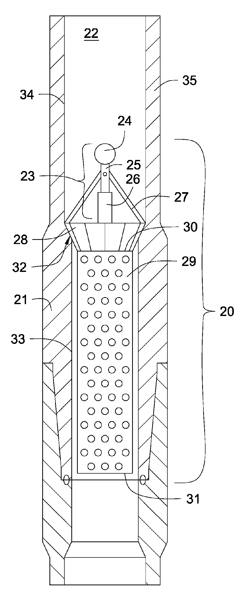
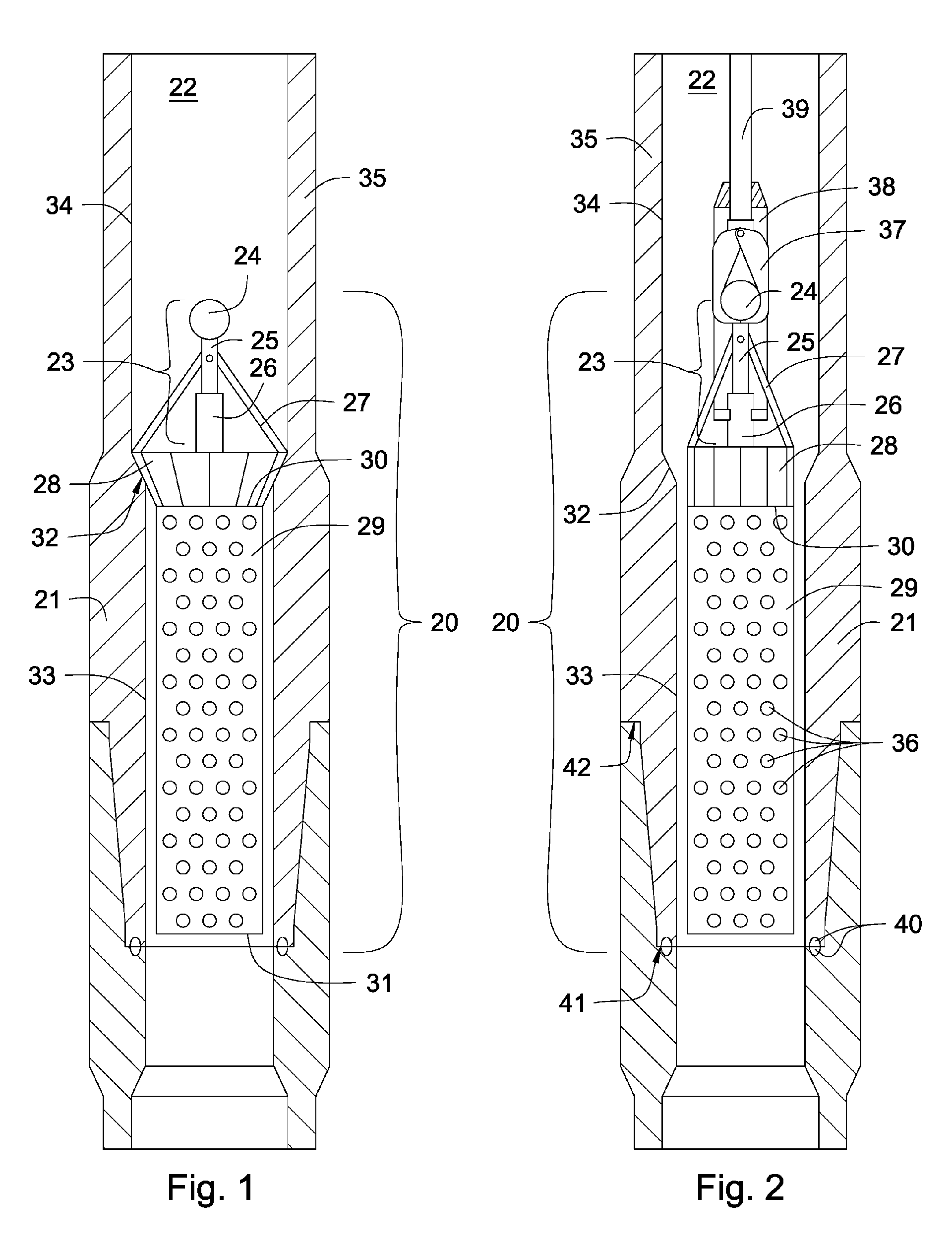
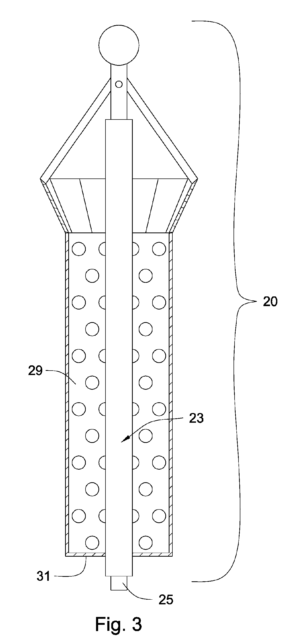
[0025]FIG. 1 is an orthogonal view of a filter 20 mounted in a bore 22 within a cross section of a drill string component 21. The filter 20 comprises a perforated receptacle 29 with an open end 30 and a closed end 31. The closed end 31 may also be perforated. The perforated receptacle 29 may comprise a generally cylindrical shape, a generally rectangular shape, a generally conical shape, a generally spherical shape, or an amorphous shape. A hanger 28 is fixedly positioned against an internal upset 32 of the bore wall 35 intermediate a first internal diameter 33 and a second internal diameter 34 of the bore wall 35. The filter 20 further comprises a mandrel 23 with a stationary portion 26 attached to the open end 30 of the filter 20, a telescopic adjustable portion 25 attached to linkages 27, and a top-hole interface 24 for removable attachment to top-hole equipment. The linkages 27 may be selected from the group consisting of struts, articulated struts, and cams. The adjustable port...


PUM


Abstract

A drilling fluid filter for placement within a bore wall of a tubular drill string component comprises a perforated receptacle with an open end and a closed end. A hanger for engagement with the bore wall is mounted at the open end of the perforated receptacle. A mandrel is adjacent and attached to the open end of the perforated receptacle. A linkage connects the mandrel to the hanger. The linkage may be selected from the group consisting of struts, articulated struts and cams. The mandrel operates on the hanger through the linkage to engage and disengage the drilling fluid filter from the tubular drill string component. The mandrel may have a stationary portion comprising a first attachment to the open end of the perforated receptacle and a telescoping adjustable portion comprising a second attachment to the linkage. The mandrel may also comprise a top-hole interface for top-hole equipment.

Description

FEDERAL SPONSORSHIP [0001] This invention was made with government support under Contract No. DE-FC26-01 NT41229 awarded by the U.S. Department of Energy. The government has certain rights in the invention.BACKGROUND OF THE INVENTION [0002] As drilling mud is recirculated during drilling, debris from earth formations may damage sensitive downhole equipment. Filters used to collect the debris and thereby provide a way of removing the debris are known in the art. Often these filters will attach in single shouldered pipe such as described in U.S. Pat. No. 4,495,073. The '073 patent discloses a mud screen for installation between any two selected ends of interconnected pipes comprising a supporting collar anchored in the selected threaded connection of the drill pipe string and a screen support mounted on such collar and secured thereto by one or more releasing devices. An apertured inverted conical screen is supported by the screen support in transverse relationship to the pipe bore. A...

Claims


Application Information

Patent Timeline
IPC IPC(8): E21B31/113E21B43/34
CPCE21B21/002
Inventor HALLFOX, JOEGARNER, KORY
Owner INTELLISERV
Why Eureka
Try Eureka