
Temperature control system

a temperature control and control system technology, applied in ventilation systems, heating types, domestic cooling apparatuses, etc., can solve problems such as inability to use pid control systems, and achieve the effect of fast and effective temperature control and/or regulation

Inactive Publication Date: 2006-03-30
AIRBUS OPERATIONS GMBH
View PDF8 Cites 9 Cited by
  • Summary
  • Abstract
  • Description
  • Claims
  • Application Information

AI Technical Summary

Benefits of technology

[0006] It is believed that this exemplary embodiment of the present invention may provide for a utilization of the non-linearity of a fuzzy control, wherein an output value may vary even if the difference between two controlled quantities, which are used for calculating the output value (the control variable), is constant. This may not be possible with a PID control system. Furthermore, the control circuits may be designed in the form of a feed-forward closed-loop regulation circuit so that fast control and / or regulation may be achieved.
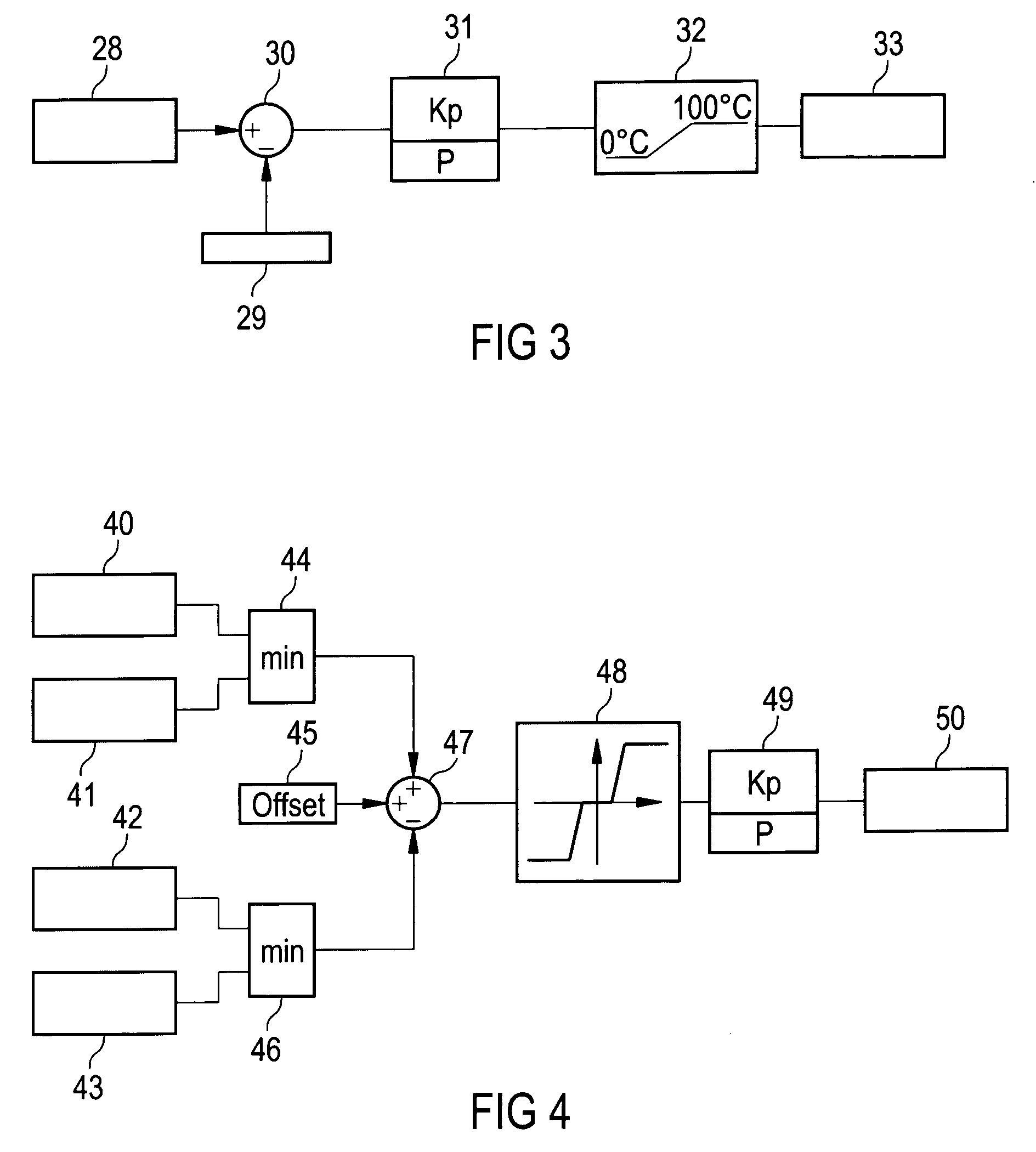
[0011] According to a further exemplary embodiment of the present invention, non-linear fuzzy logic for calculating the control variables from the set variables is based on AND operations and centroid methods. Advantageously, this process may provide for a fast, effective and flexible method for calculating the control variables.
[0013] It is believed that this controlling apparatus may be integrated into a commercial aircraft and may be adapted to set the temperature in various cells. These cells may for example comprise the cockpit, sanitary cells, and seating areas for the aircrew and passengers. By using non-linear fuzzy logic within the controlling circuit and a multitude of regulated quantities or set variables for calculating the control variables, which are used for controlling the controlling devices, for example fluctuations in the temperature of the incoming air can advantageously be incorporated into the calculation of the control variables, and fast and effective temperature control and / or regulation may be provided.

Problems solved by technology

This may not be possible with a PID control system.

Method used


Image

  • Temperature control system
  • Temperature control system
  • Temperature control system

Examples


Embodiment Construction

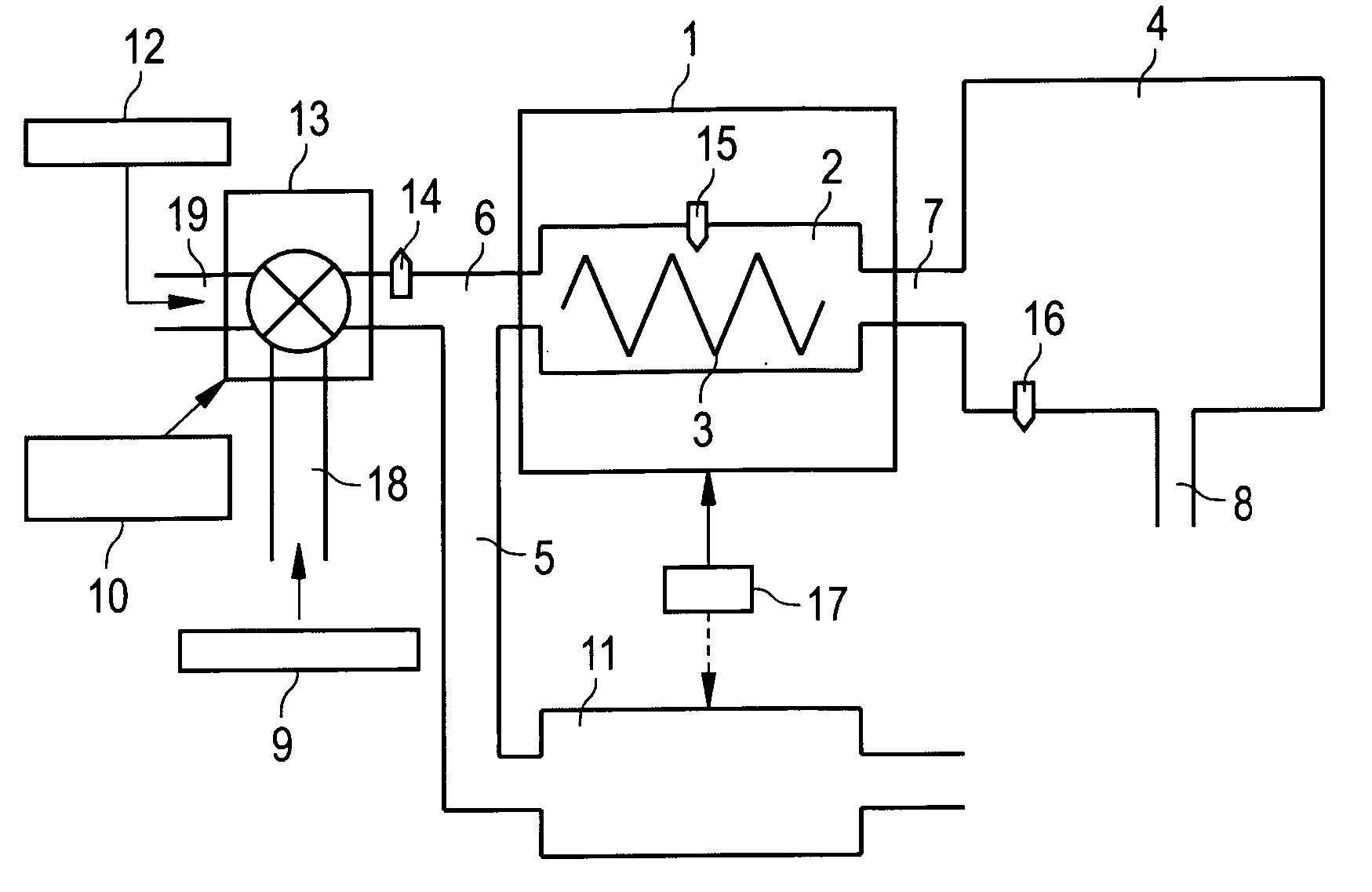
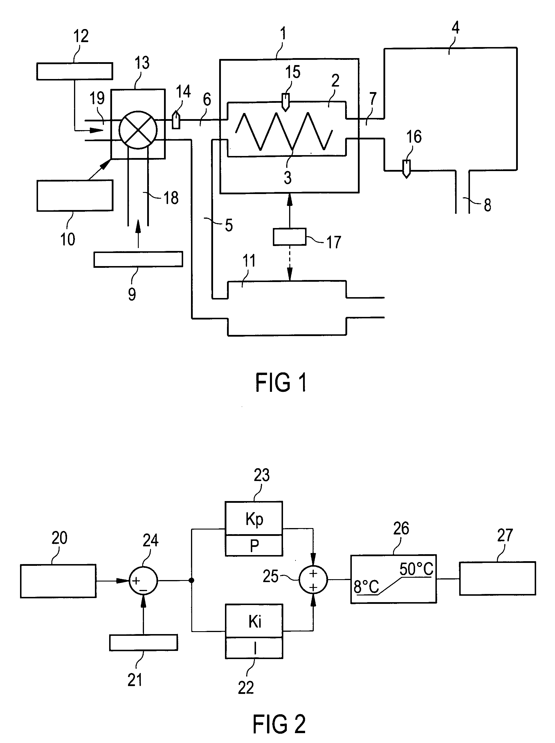
[0027]FIG. 1 is a diagrammatic representation of a regulating device for regulating the temperature in a space comprising one or several cells 4. The incoming air from an air mixer 12 and a bleed air compressor 9 is intermixed by means of a trim adjustment valve 13, wherein the trim adjustment valve 13 regulates the fractions of hot air emanating from the bleed air compressor 9 and cold air emanating from the air mixer 12. Furthermore, the trim adjustment valve 13 regulates the quantity passing through and thus the pressure in the cell 4. The trim adjustment valve 13 is controlled by means of the control device 10 which comprises a processor.

[0028] The airflow, which has been set by means of the trim adjustment valve 13, is now led into a heater 1 by means of the pipeline or duct 6. In its heating chamber 2, the heater 1 comprises heating elements 3 so that the air flowing through can be heated. Such heaters 1 are well known in the state of the art and are not described in further ...


PUM


Abstract

Temperature regulation by means of a PID regulation method can be associated with disadvantageous oscillations, overshooting and long control times. According to an exemplary embodiment of the present invention, during temperature regulation of a space, non-linear fuzzy logic is provided which for intelligent temperature regulation uses extensive information from the environment. Such information includes in particular the temperature in the air inlet duct upstream of the heater, and the rate of change in the temperature in the air inlet duct upstream of the heater and in a first cell of the space. In this way, a fast and precise temperature regulating system may be provided which largely prevents or suppresses undesirable oscillations.

Description

BACKGROUND OF THE INVENTION [0001] The present invention relates to a temperature control system. In particular, the present invention relates to a method for controlling the temperature in a space comprising one or more cells, a controlling device for controlling the temperature in a space comprising one or more cells, and a computer program for controlling a heating system. [0002] In the case of commercial aircrafts, incoming air is channelled through a heater and is correspondingly heated before it enters a space whose temperature is to rise. This space can for example be a compartment which houses the seats for passengers. [0003] The air introduced into the heater is in known devices and methods intermixed from air emanating from an air mixer and from air emanating from a bleed air compressor. This intermixture is regulated by a so-called trim adjustment valve (TAV). Both the trim adjustment valve and the heater are controlled by way of their own regulating loop, with the use of...

Claims


Application Information

Patent Timeline
IPC IPC(8): F24F7/00B64D13/08F24F11/00G05B13/02G05D23/19
CPCB64D13/08Y10S62/05G05D23/1917G05B13/0275
Inventor FAURET, JEAN REMY
Owner AIRBUS OPERATIONS GMBH
Learn More