
Capture and display of image of three-dimensional object

a three-dimensional object and image technology, applied in the field of system and method for displaying an image of a three-dimensional object, to achieve the effect of real-time viewing experien

Inactive Publication Date: 2006-03-30
BENZANO DANIEL
View PDF12 Cites 48 Cited by
  • Summary
  • Abstract
  • Description
  • Claims
  • Application Information

AI Technical Summary

Benefits of technology

The present invention provides a system and method for creating a realistic and visually appealing model of an object using a combination of geometric and reflectivity information. The system includes a modeling mechanism for creating a geometric model of the object and an imaging mechanism for obtaining a plurality of reflectivity images from different perspectives. The geometric model and reflectivity images are then combined to create a reflectivity model that includes color and texture information. The system can also include a holder for rotating the object and a vacuum mechanism for securing the object. The method involves obtaining a geometric model of the object, obtaining at least one reflectivity image, and combining the geometric model and reflectivity image to create a reflectivity model. The system and method provide a unique and immersive viewing experience for the viewer.

Problems solved by technology

However, the map provided according to U.S. Pat. No. 6,567,156 does not provide information to a viewer regarding the color or reflectivity of the surface of the object, nor is there a provision for viewing of the mapped object from arbitrary angles.

Method used


Image

  • Capture and display of image of three-dimensional object
  • Capture and display of image of three-dimensional object
  • Capture and display of image of three-dimensional object

Examples


first embodiment

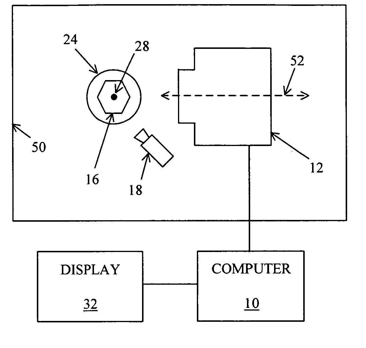
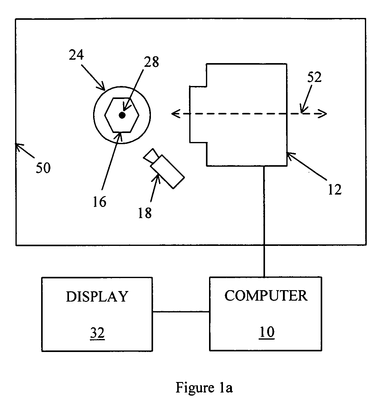
[0076] Referring now to the drawings, FIG. 1a illustrates schematically the present invention, in which an object 16 is held on a rotatable support, or dop, 24. Optionally, object 16 is coated with a preferably removable coating that diffuses light. Coating object 16 is particularly advantageous if object 16 is transparent and / or reflective. Marks can be made on the coating. If the coating is sufficiently thin and made of appropriate material, surface marks on object 16 will be visible through the coating. Preferably, object 16 is held onto dop 24 by a vacuum mechanism. An enclosure 50 is operative to suppress stray light.

[0077] Object 16 is illuminated by a lamp 18 and photographed by a camera 12, and then rotated through an angle by dop 24, the angle preferably having measure of at least 0.1 degree and no greater than 20 degrees, and, still more preferably, having measure of at least 0.5 degree and no greater than 5 degrees, the angle also preferably having measure substantially e...

second embodiment

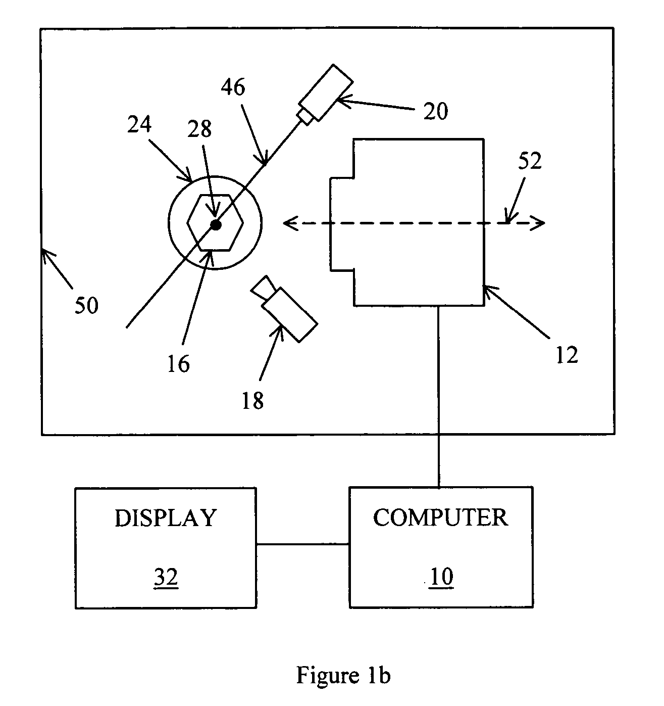
[0086] Alternatively, in this second embodiment, object 16 can be rotated a single time, with lamp 18 and structured light source 20 illuminated by turns such that camera 12 produces an interleaved set of photographs including both the information for creating the three-dimensional model and the reflectivity data.

[0087] Returning now to structured light source 20, FIG. 7a illustrates schematically an elevation view, and FIG. 7b illustrates schematically a plan view, of a system for structured lighting of object 16. For simplicity, camera 12 is not shown in FIG. 7a. Structured-light source 20 is operative to illuminate object 16 with structured light. Preferably, structured-light source 20 includes a laser 40, operative to produce a beam of light 44, and an optical system 42 operative to shape beam 44 into a structured beam 46. Preferably, structured beam 46 has a very narrow cross-section, preferably no greater than 20 μm, in the neighborhood of object 16, in a first dimension norma...


PUM


Abstract

A system and method for modeling three-dimensional objects such as diamonds and other gemstones. A three-dimensional finite-element model obtained by, for example, analysis of boundaries of the object in photographs taken from multiple perspectives with frontal lighting or silhouette lighting, or by analysis of structured-light photographs of the object taken from multiple perspectives, is combined with color or grayscale information obtained from photographs of the object. Enhanced or “false” color can be used to improve the viewing experience or to emphasize particular features of the object. A computer can rotate the model about arbitrary axes according to the desires of a viewer.

Description

[0001] This is a continuation-in-part of U.S. Provisional Patent Application No. 60 / 614,048, filed Sep. 30, 2004 and claims priority of Israel Patent Application No. 166574 filed Jan. 30, 2005.FIELD AND BACKGROUND OF THE INVENTION [0002] The present invention relates to a system and method for capturing and displaying an image of a three-dimensional object, and, more particularly, to a system and method wherein a three-dimensional finite-element model of the outer surface of the object is combined with photographs of the object taken from multiple angles and displayed on a display device such as a computer screen. The photographic data are used to assign color or grayscale values to the elements of the three-dimensional model. The object is then displayed using a combination of the information from the three-dimensional model and the color or grayscale values, providing a realistic view of the object, including any surface markings. The three-dimensional model can be rotated about a...

Claims


Application Information

Patent Timeline
Patent Type & Authority Applications(United States)
IPC IPC(8): G01B11/24
CPCG01N21/87G06T1/0007G01B11/25
Inventor BENZANO, DANIEL
Owner BENZANO DANIEL
Learn More