Inlet airflow guiding structure for computers

Active Publication Date: 2006-03-30
SHUTTLE
View PDF11 Cites 5 Cited by
  • Summary
  • Abstract
  • Description
  • Claims
  • Application Information

AI Technical Summary

Benefits of technology

[0006] Accordingly, the inlet airflow guiding structure of the present invention including an airflow guiding space defined between the front bezel and the computer chassis, and a plurality of inlet airflow openings can provide a low airflow impedance inlet that facilitates the movement of the incoming inlet airflow. Therefore, as the computer uses a front-to-back airflow disposit

Problems solved by technology

Furthermore, it is unnecessary to bore a large diameter airflow opening on

Method used


Image

  • Inlet airflow guiding structure for computers
  • Inlet airflow guiding structure for computers
  • Inlet airflow guiding structure for computers

Examples


Example

[0015] Reference will now be made in detail to the preferred embodiments of the present invention, examples of which are illustrated in the accompanying drawings. Wherever possible, the same reference numbers are used in the drawings and the description to refer to the same or like parts.

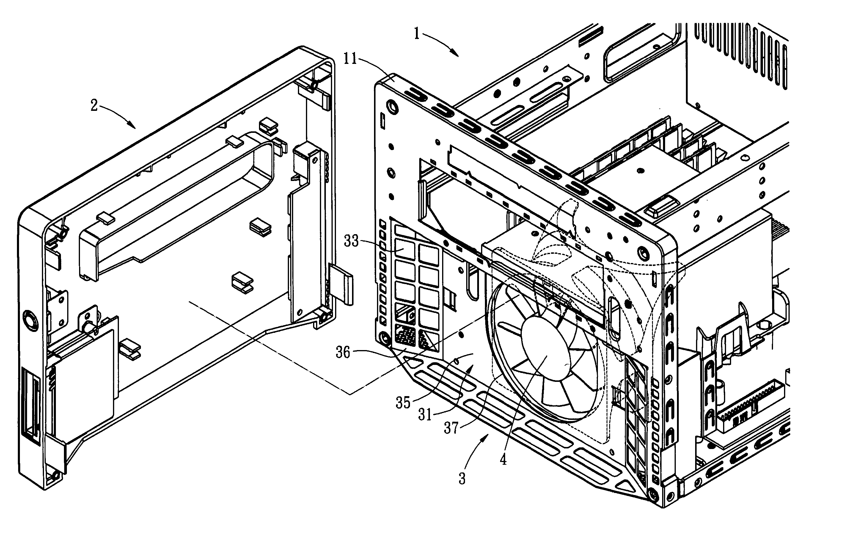
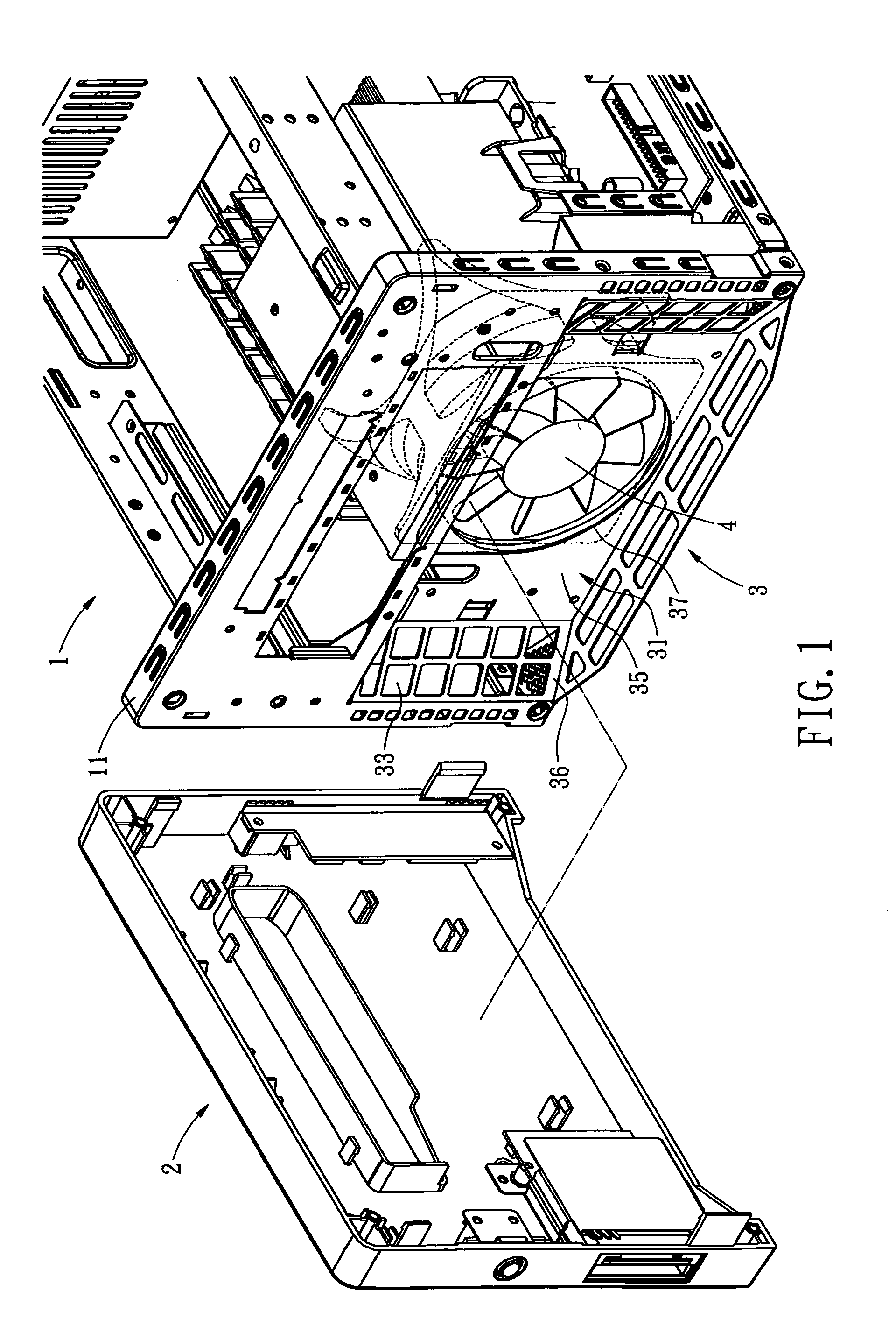
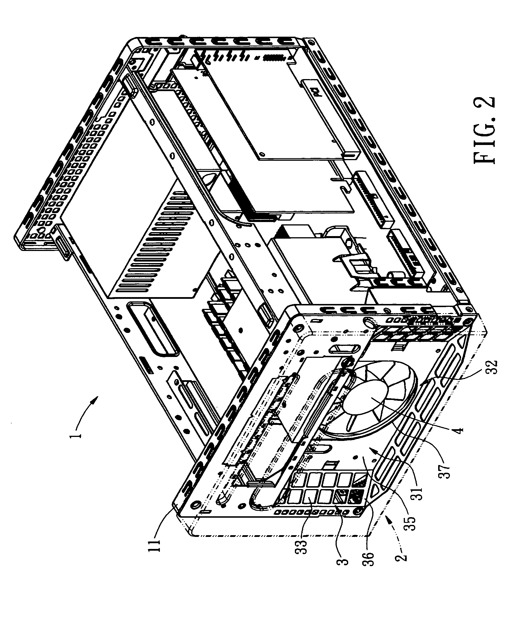
[0016] Referring to FIGS. 1 though 5, an inlet airflow guiding structure for computers according one preferred embodiment of the present invention is illustrated. The inlet airflow guiding structure 3 includes a computer chassis 1, a front bezel 2 which connects to the computer chassis 1, an airflow guiding space 32, and a plurality of inlet airflow openings 33, 34. The computer provides a front-to-back airflow disposition by utilizing a front cooling fan 4 which is installed at the front panel 11 of the computer chassis 1. This front-to-back airflow disposition complies with the BTX specification suggested by the Intel Corporation.

[0017] The inlet airflow guiding structure of the present inventio...


PUM


Abstract

An inlet airflow guiding structure for a computer includes a computer chassis, a front bezel, an airflow guiding space defined between the front bezel and the computer chassis, and a plurality of inlet airflow openings. The airflow guiding space and the inlet airflow openings provide a low airflow impedance inlet that facilitates the movement of the incoming inlet airflow. The front cooling fan in the computer is thereby capable of providing lower-temperature air into computer for efficiently dissipating heat generated for high-speed CPU.

Description

BACKGROUND OF THE INVENTION [0001] The present invention relates in general to an inlet airflow guiding structure for computers, and more particularly, to an inlet airflow guiding structure utilized in a computer that complies with the Balanced Technology Extended (BTX) Interface Specification suggested by the Intel Corporation, and capable of rapidly introducing external cool air into computer to provide efficiently heat dissipating. [0002] Various electrical instruments, especially the desktop computers, are crowded with different electrical components and peripheral devices, such as the Central Processing Unit (CPU), the interface card, the hard disk, the disk burner, and the power supply. Those electrical components and peripheral devices each generate different levels of heat during their respective operations. The CPU because of its high processing speed, in particular, generates a large amount of heat. Nonetheless, the computer case of the average desktop computer is closed. ...

Claims


Application Information

Patent Timeline
IPC IPC(8): H05K7/20
CPCG06F1/181H05K7/20572G06F1/20
Inventor YU, WEN-LUNGLAI, RAY-MING
Owner SHUTTLE
Why Eureka
Try Eureka