Photoacoustic measurement probe and probe unit and photoacoustic measurement apparatus including the same

Active Publication Date: 2018-07-19
FUJIFILM CORP
View PDF0 Cites 1 Cited by
  • Summary
  • Abstract
  • Description
  • Claims
  • Application Information

AI Technical Summary

Benefits of technology

[0025]The photoacoustic measurement probe of the present invention comprises the first heat conductive member that is in contact with a part of the side plate and the amplifier to transfer the heat generated by the amplifier to the side plate and the second heat conductive member that is in contact with a part different from the part of the side plate and the acoustic w

Problems solved by technology

Since the probe disclosed in JP2008-043440A does not have a configuration for detecting a photoacoustic wave, it is

Method used


Image

  • Photoacoustic measurement probe and probe unit and photoacoustic measurement apparatus including the same
  • Photoacoustic measurement probe and probe unit and photoacoustic measurement apparatus including the same
  • Photoacoustic measurement probe and probe unit and photoacoustic measurement apparatus including the same

Examples


first embodiment

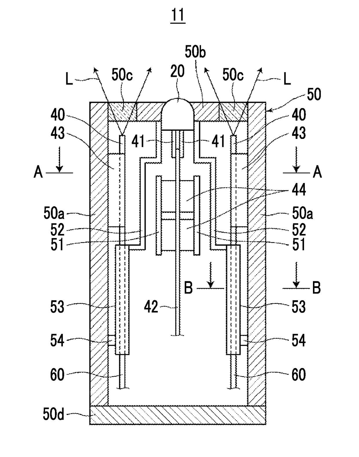
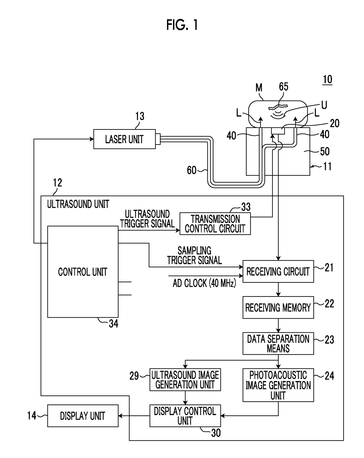
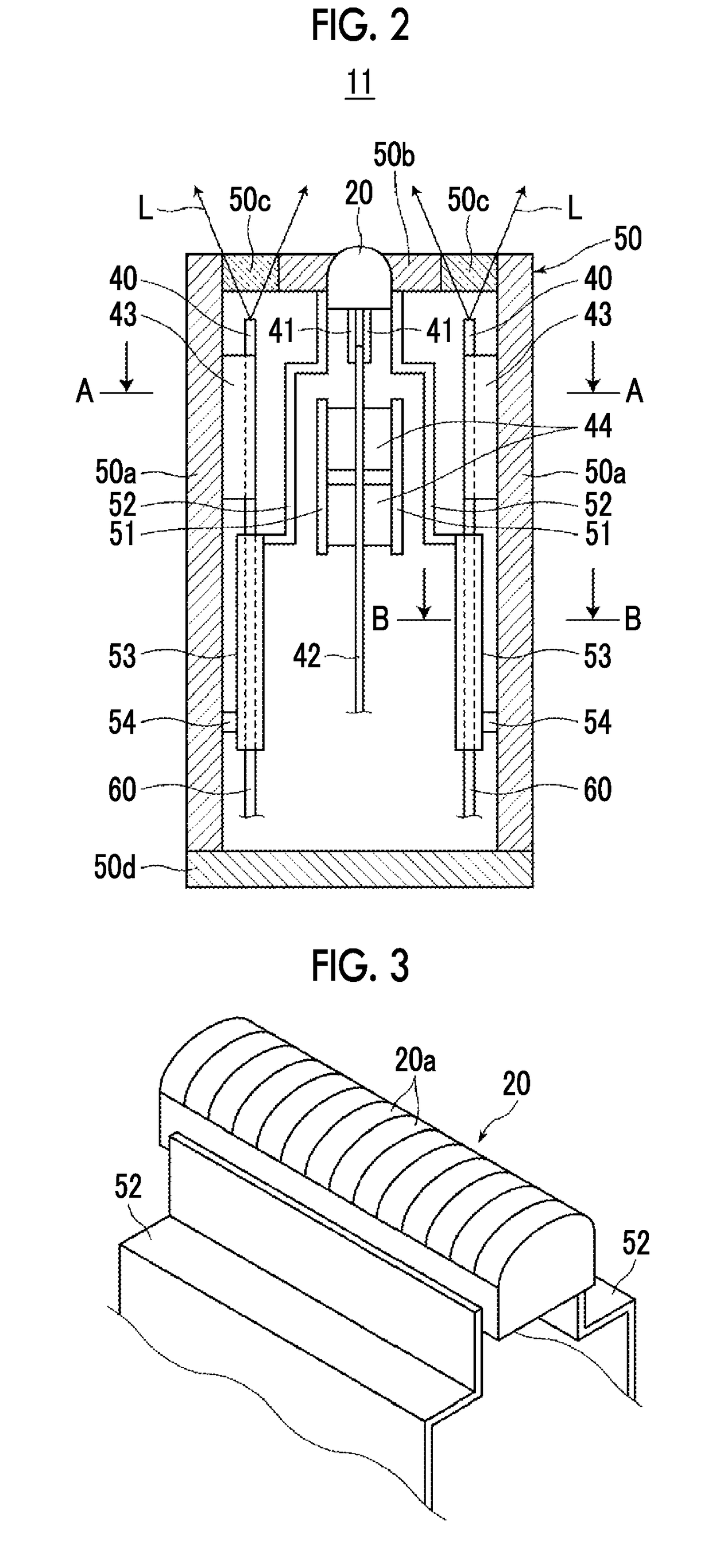
[0042]First, a photoacoustic measurement probe, a probe unit, and a photoacoustic measurement apparatus according to a first embodiment of the present invention will be described. FIG. 1 is a schematic diagram showing the overall configuration of a photoacoustic measurement apparatus 10 of the present embodiment. FIGS. 2 and 3 are a side cross-sectional view and a partial perspective view showing a photoacoustic measurement probe (hereinafter, simply referred to as a probe) 11 used in the photoacoustic measurement apparatus 10, respectively. FIG. 4 is a horizontal cross-sectional view showing a cross section taken along the line A-A in FIG. 2, and FIG. 5 is a horizontal cross-sectional view showing a cross section taken along the line B-B in FIG. 2. In FIG. 1, the shape of the probe 11 is schematically shown.

[0043]As an example, the photoacoustic measurement apparatus 10 of the present embodiment has a function of generating a photoacoustic image based on a photoacoustic signal, and...

second embodiment

[0088]Next, a probe 211 according to a second embodiment of the present invention will be described with reference to FIG. 6. FIG. 6 shows the side cross-sectional shape of the probe 211 of the present embodiment. In FIG. 6, the same elements as in FIG. 2 described previously are denoted by the same reference numerals, and the explanation thereof will be omitted unless particularly required (the same hereinbelow). The probe 211 is different from the probe 11 shown in FIG. 2 in terms of the configuration of the second heat conductive member. That is, in the present embodiment, instead of the fiber fixing member 43 shown in FIG. 2, a fiber fixing member 55 formed of a high heat conductivity material is applied. As specific examples of such a high heat conductivity material, it is possible to apply pyrolytic graphite, such as aluminum, stainless steel, and “PGS graphite sheet” manufactured by Panasonic Electronic Devices Co., Ltd., high heat conductivity resin represented by “3M (regis...

third embodiment

[0093]Next, a probe 311 according to a third embodiment of the present invention will be described with reference to FIG. 7. FIG. 7 shows the side cross-sectional shape of the probe 311 of the present embodiment. The probe 311 is basically different from the probe 211 shown in FIG. 6 in that a heat transfer plate 58 having one end portion and the other end portion tightly fixed to the transducer array 20 and the fiber fixing member 55, respectively, is used instead of the heat transfer plate 52 and the heat transfer member 53 is omitted. Since the heat transfer member 53 is omitted, a simple plate-shaped frame member 57 is used, which is somewhat different from the frame member 56 in the configuration shown in FIG. 6.

[0094]In the configuration described above, heat generated mainly from the preamplifier 44 is satisfactorily transferred to the two side plates 50a through the heat transfer plate 51. In addition, heat generated mainly from the transducer array 20 is satisfactorily tran...


PUM


Abstract

In a photoacoustic measurement probe including an acoustic wave detector and an amplifier for amplifying a detection signal of a photoacoustic wave and a probe unit and a photoacoustic measurement apparatus having such a probe, heat is efficiently dissipated from the probe.
In a probe having an acoustic wave detector and an amplifier, there are provided a first heat conductive member that is in contact with a part of a side plate of a housing and the amplifier to transfer heat generated by the amplifier to the side plate and a second heat conductive member that is in contact with a part different from the part of the side plate and the acoustic wave detector to transfer heat generated by the acoustic wave detector to the side plate.

Description

CROSS-REFERENCE TO RELATED APPLICATION[0001]This application is a continuation application of International Application No. PCT / JP2016 / 004110, filed Sep. 9, 2016, the disclosure of which is incorporated herein by reference in its entirety. Further, this application claims priority from Japanese Patent Application No. 2015-184762 filed Sep. 18, 2015, the disclosure of which is incorporated herein by reference in its entirety.BACKGROUND OF THE INVENTION1. Field of the Invention[0002]The present invention relates to a photoacoustic measurement probe that emits light toward a subject and absorbs the light to detect photoacoustic waves generated within the subject.[0003]In addition, the present invention relates to a probe unit and a photoacoustic measurement apparatus including such a probe.2. Description of the Related Art[0004]In recent years, a non-invasive measurement method using a photoacoustic effect has been drawing attention. In the measurement method, a photoacoustic wave, whi...

Claims


Application Information

Patent Timeline
IPC IPC(8): A61B5/00A61B8/00
CPCA61B5/0095A61B5/0059A61B8/4444A61B8/13A61B8/4494A61B8/546
Inventor HASHIMOTO, ATSUSHIIRISAWA, KAKUOSAWA, ATSUSHI
Owner FUJIFILM CORP
Why Eureka
Try Eureka