Illuminator with a radiator

Active Publication Date: 2021-04-22
CHANGZHOU KAISEN PHOTOELECTRICITY CO LTD +1
View PDF0 Cites 1 Cited by
  • Summary
  • Abstract
  • Description
  • Claims
  • Application Information

AI Technical Summary

Benefits of technology

[0004]It is the primary objective of the present invention

Problems solved by technology

The life of a light-emitting diode (“LED”) is jeopardized due to poor dissipation of heat.
However, the dissipation of heat produced by the LED illum

Method used


Image

  • Illuminator with a radiator
  • Illuminator with a radiator
  • Illuminator with a radiator

Examples


Embodiment Construction

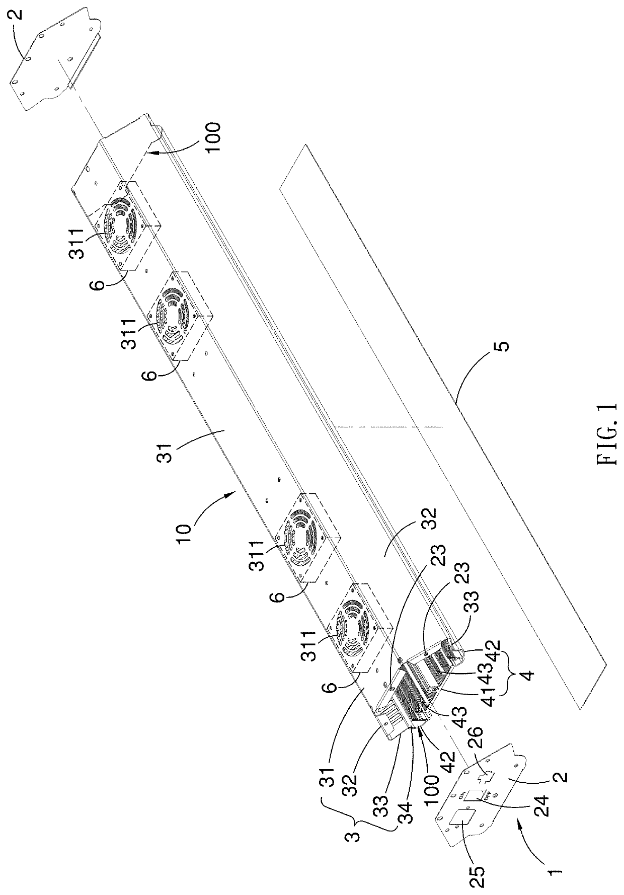
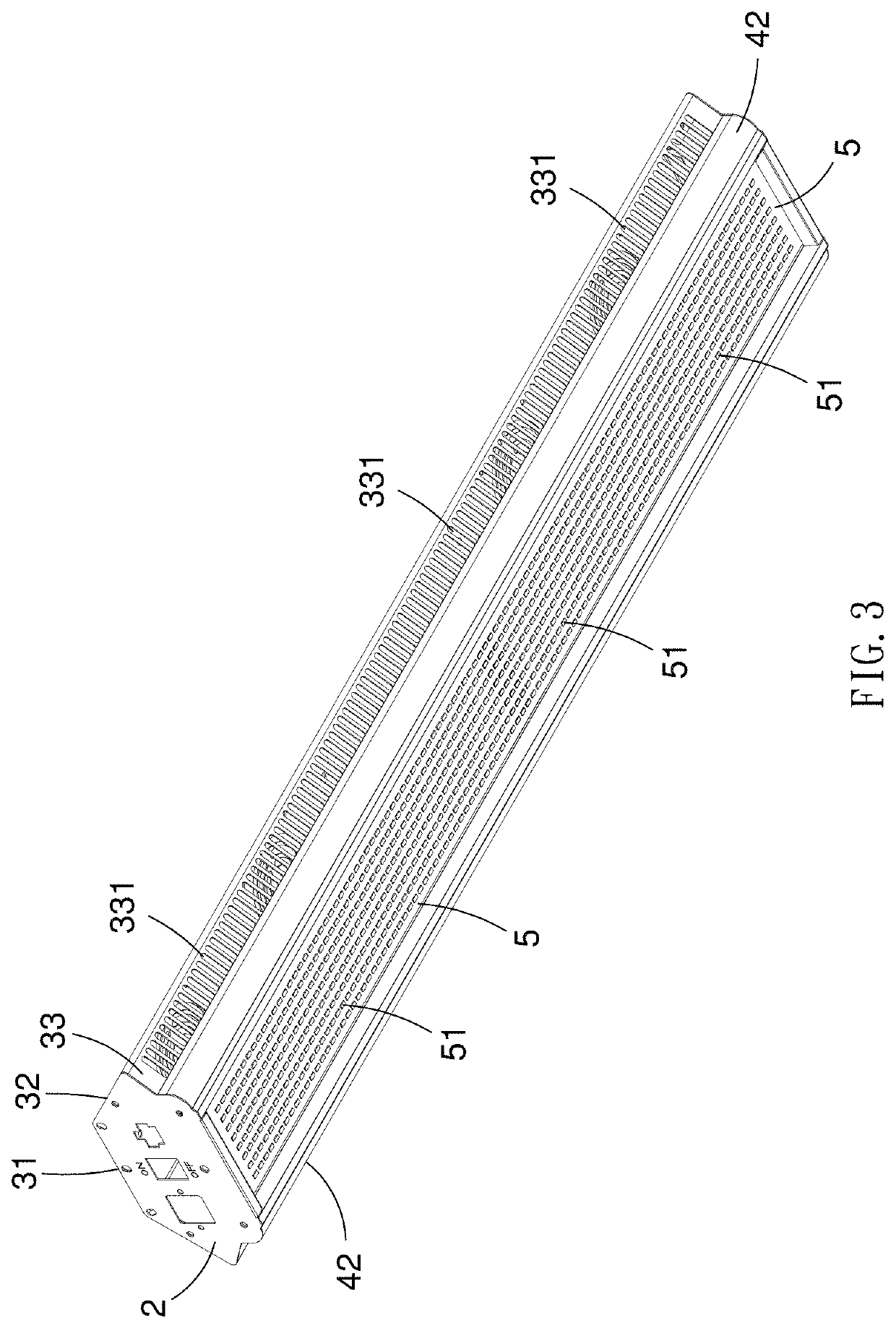
[0027]Referring to FIGS. 1 through 5, an illuminator includes a housing 1, several fans 6 and an LED array 5 according to a first embodiment of the present invention. The housing 1 includes two lateral plates 2, an upper shell 3 and a lower shell 4. The upper shell 3 is connected to the lower shell 4 to provide a tubular structure 10. The lateral plates 2 are attached to two opposite open ends of the tubular structure 10. The upper shell 3 is connected to the lower shell 4 by buckles or screws for example. Similarly, the lateral plates 2 are connected to the tubular structure 10 by buckles or screws.

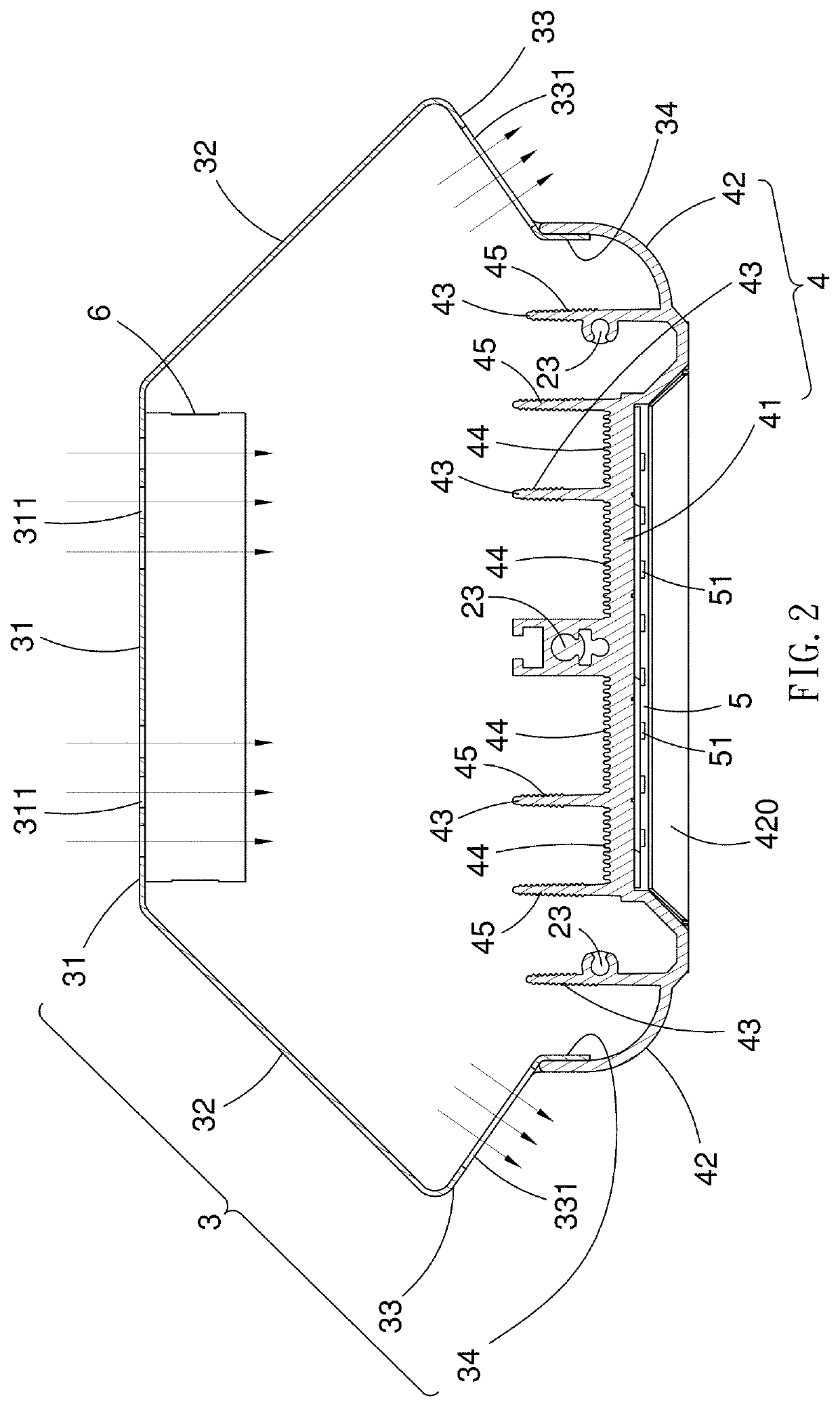
[0028]Referring to FIGS. 1 and 2, the upper shell 3 includes an inlet portion 31, two connective portions 32, two outlet portions 33 and two extensive portions 34. The connective portions 32 extend from two opposite edges of the inlet portion 31. Each of the outlet portions 33 extends from an edge of a corresponding one of the connective portions 32. Each of the extensive portions 34 ext...


PUM


Abstract

An illuminator includes an upper shell, a lower shell, an LED array and at least one fan. The upper shell includes a first outlet portion extending downward and inward from an inlet portion. The inlet portion includes at least one entrance. The first outlet portion includes a row of vents. The lower shell is made of thermally conductive metal and includes primary radiator fins extending from an upper face of a substrate. The lower shell is connected to the upper shell to form a tubular structure. The LED array is connected to a lower face of the lower shell and includes light-emitting diodes. The at least one fan is inserted in the tubular structure, connected to the inlet portion, and aligned with the at least one aperture.

Description

BACKGROUND OF INVENTION1. Field of Invention[0001]The present invention relates to illuminators and, more particularly, to an illuminator with a radiator.2. Related Prior Art[0002]The life of a light-emitting diode (“LED”) is jeopardized due to poor dissipation of heat. To solve this problem, an LED illuminator can be equipped with fans as disclosed in Chinese Patent No. CN202674955U and Taiwanese Patent No. M507652 for example. However, the dissipation of heat produced by the LED illuminators particularly those used to promote the growth of plants is not satisfactory. Moreover, the structures of the LED illuminators are complicated.[0003]The present invention is therefore intended to obviate or at least alleviate the problems encountered in prior art.SUMMARY OF INVENTION[0004]It is the primary objective of the present invention to provide an illuminator that effectively dissipates heat.[0005]To achieve the foregoing objective, the illuminator includes an upper shell, a lower shell,...

Claims


Application Information

Patent Timeline
IPC IPC(8): F21V29/76F21V29/67F21K9/275
CPCF21V29/763F21Y2115/10F21K9/275F21V29/677A01G9/249F21Y2105/16F21Y2103/20
Inventor XU, YAOPING
Owner CHANGZHOU KAISEN PHOTOELECTRICITY CO LTD
Why Eureka
Try Eureka