Thermosiphon for laptop computer

Inactive Publication Date: 2008-10-02
COOLIT SYSTEMS INC
View PDF11 Cites 2 Cited by
  • Summary
  • Abstract
  • Description
  • Claims
  • Application Information

AI Technical Summary

Benefits of technology

[0011]Accordingly, the invention provides an alternative design for a thermosiphon that occupies a minimum of space yet efficiently dissipates heat and can be manufactured from stock parts, or efficiently formed parts. The condensing

Problems solved by technology

Heat exchangers and heat sink assemblies have been used that apply natural or forced convection cooling methods to dissipate heat from electronic elements that are highly concentrated heat sources such as microprocessors and computer chips; however, air has a relatively low heat capacity.
Ho

Method used


Image

  • Thermosiphon for laptop computer
  • Thermosiphon for laptop computer

Examples


Example

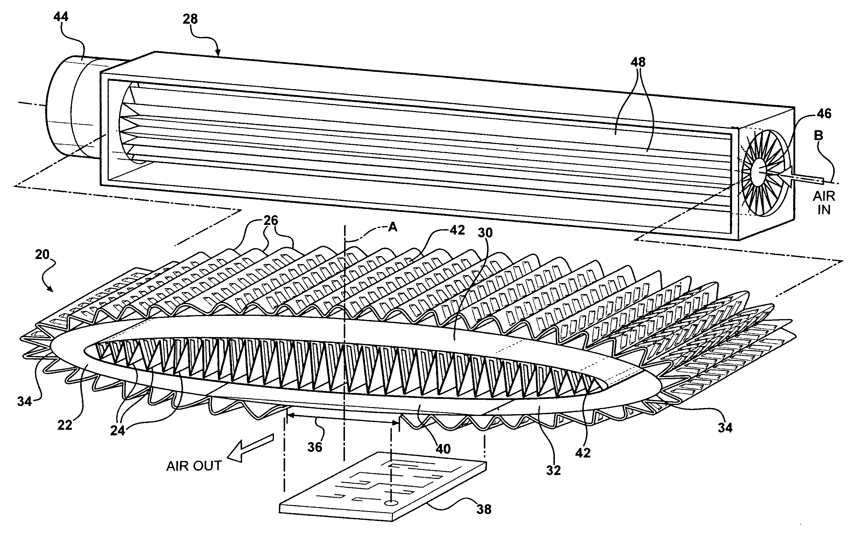
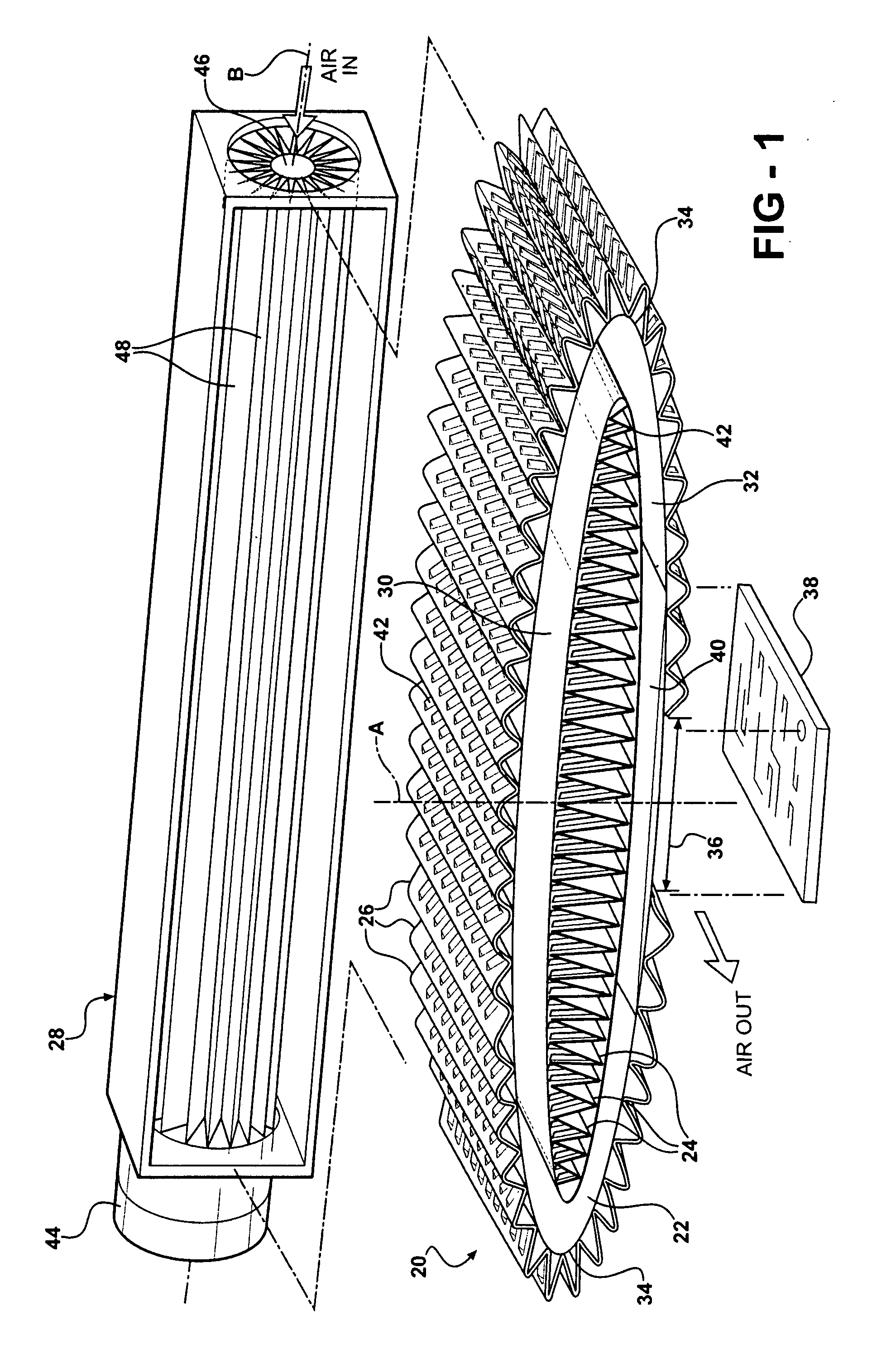
[0013]Referring to the Figure, a heat exchanger assembly 20 is generally shown for cooling an electronic element.

[0014]The assembly 20 includes a condensing tube 22 generally indicated extending in an endless loop. A plurality of internal fins 24 extend within the endless loop of the tube 22 for dissipating heat. A plurality of corrugated external fins 26 extend around the outside of the condensing tube 22, also for dissipating heat. A cross-flow fan assembly 28 generally indicated may be supported adjacent to the tube 22 for moving ambient air through the internal fins 24 and the external fins 26. Persons skilled in the art will appreciate that an axial fan may be used instead of the indicated cross-flow fan assembly 28 to move ambient air through the internal and external fins 24, 26.

[0015]The endless loop of the condensing tube 22 defines an oblong shape having an upper chamber 30 and a lower chamber 32 extending from a center axis A to reverse bends defining opposite ends 34 of ...


PUM


Abstract

A heat exchanger assembly for cooling an electronic element includes an oblong condensing tube extending between ends to define an upper chamber downwardly bowed through an upwardly extending arc and a lower chamber upwardly bowed through a downwardly extending arc for dissipating heat. A continuous sheet extends in v-shaped fins between and engaging said arcs of said chambers. The internal fins extend from a center axis of the tube to reverse bends defining the opposite ends of the tube. A continuous sheet extending in sinuous corrugations extends around the exterior of the endless loop between opposite sides of a heat transfer area, which receives the electronic element.

Description

BACKGROUND OF THE INVENTION[0001]1. Field of the Invention[0002]This invention relates to a heat exchanger assembly for cooling an electronic element.[0003]2. Description of the Prior Art[0004]The operating speed of computers is constantly being improved to create faster computers. With this, comes an increase in heat generation and a need to effectively dissipate that heat.[0005]Heat exchangers and heat sink assemblies have been used that apply natural or forced convection cooling methods to dissipate heat from electronic elements that are highly concentrated heat sources such as microprocessors and computer chips; however, air has a relatively low heat capacity. Thus, liquid-cooled units called LCUs employing a cold plate in conjunction with high heat capacity fluids have been used to remove heat from these types of heat sources. Although, LCUs are satisfactory for moderate heat flux, increasing computing speeds have required more effective heat sink assemblies.[0006]Thermosiphon ...

Claims


Application Information

Patent Timeline
IPC IPC(8): H05K7/20F28D15/00
CPCF28D15/0266G06F1/20G06F1/203H01L23/427H01L2924/0002H01L2924/00
Inventor JOSHI, SHRIKANT MUKUNDBHATTI, MOHINDER SINGHREYZIN, ILYA
Owner COOLIT SYSTEMS INC
Why Eureka
Try Eureka