Air cleaner

Inactive Publication Date: 2007-06-28
EXTENIX CORP
9 Cites 3 Cited by

AI-Extracted Technical Summary

Problems solved by technology

It cannot remove dust or germs from air.
The use of such a wire gauze filter in the air outlet cannot prohibit adherence of dust to the electric fan inside the air cleaner.
When the shaft, fan ...

Method used

[0021] Further, a sound absorbing member 60, for example, a sound absorbing sponge is sandwiched between t...

Benefits of technology

[0008] According to another aspect of the present invention, the housing is made out of aluminum that dissipates heat from the at least one electric fan into the outside air efficiently.
[0009] According to still another aspect of the present invent...

Abstract

An air cleaner includes a housing having an air inlet and an air outlet, a casing mounted inside the housing and holding a first filter element with wire gauzes and a second filter element with active carbons at different elevations for removing solid matters and germs from currents of air passing from the air inlet toward the air outlet, two electric fans mounted on two ends of the casing for drawing currents of air into the inside of the housing through the air inlet toward the air outlet, a negative ion generator and an ultraviolet lamp mounted inside the housing for sterilizing currents of air passing through the housing.

Application Domain

Technology Topic

Image

  • Air cleaner
  • Air cleaner
  • Air cleaner

Examples

  • Experimental program(1)

Example

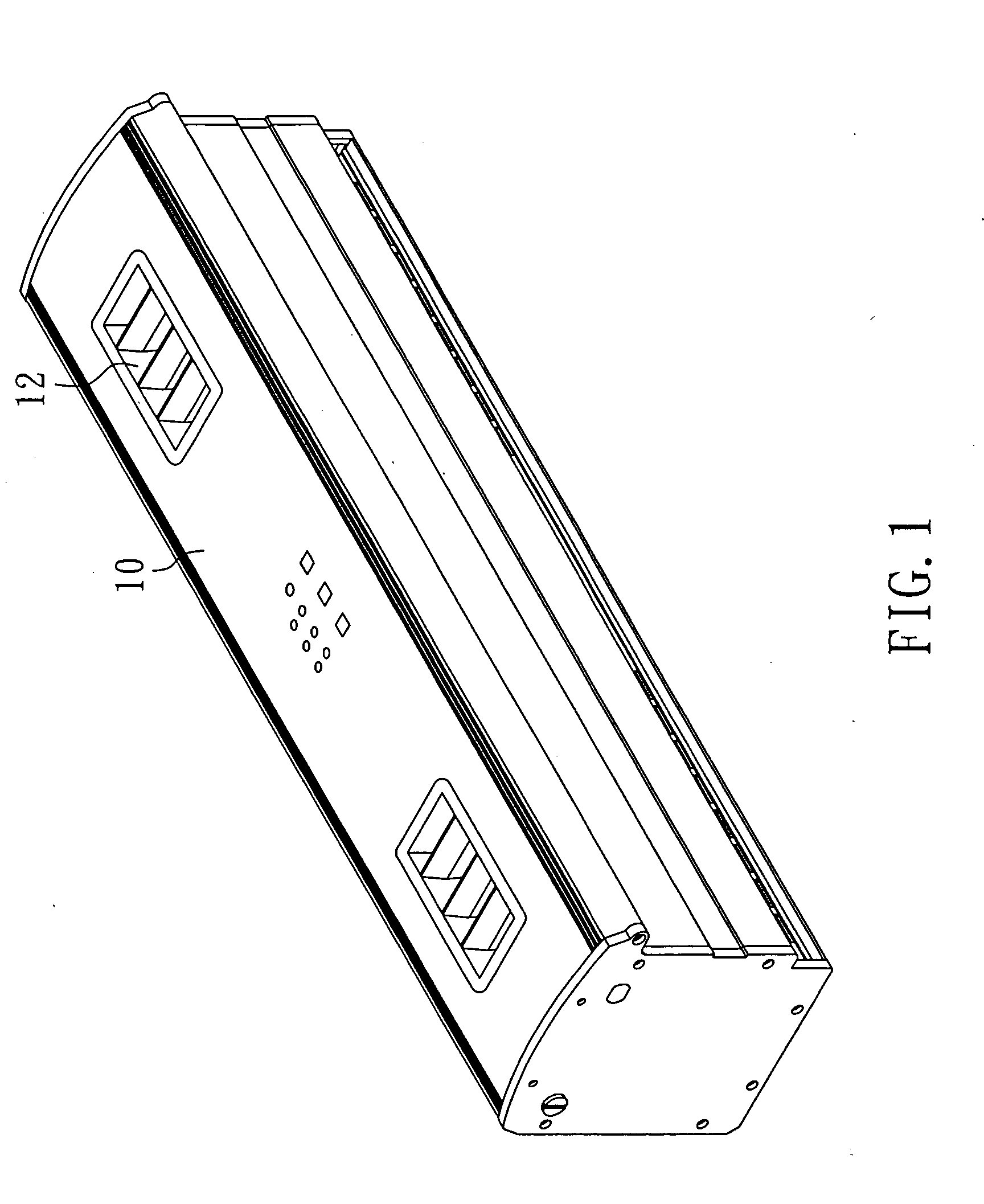
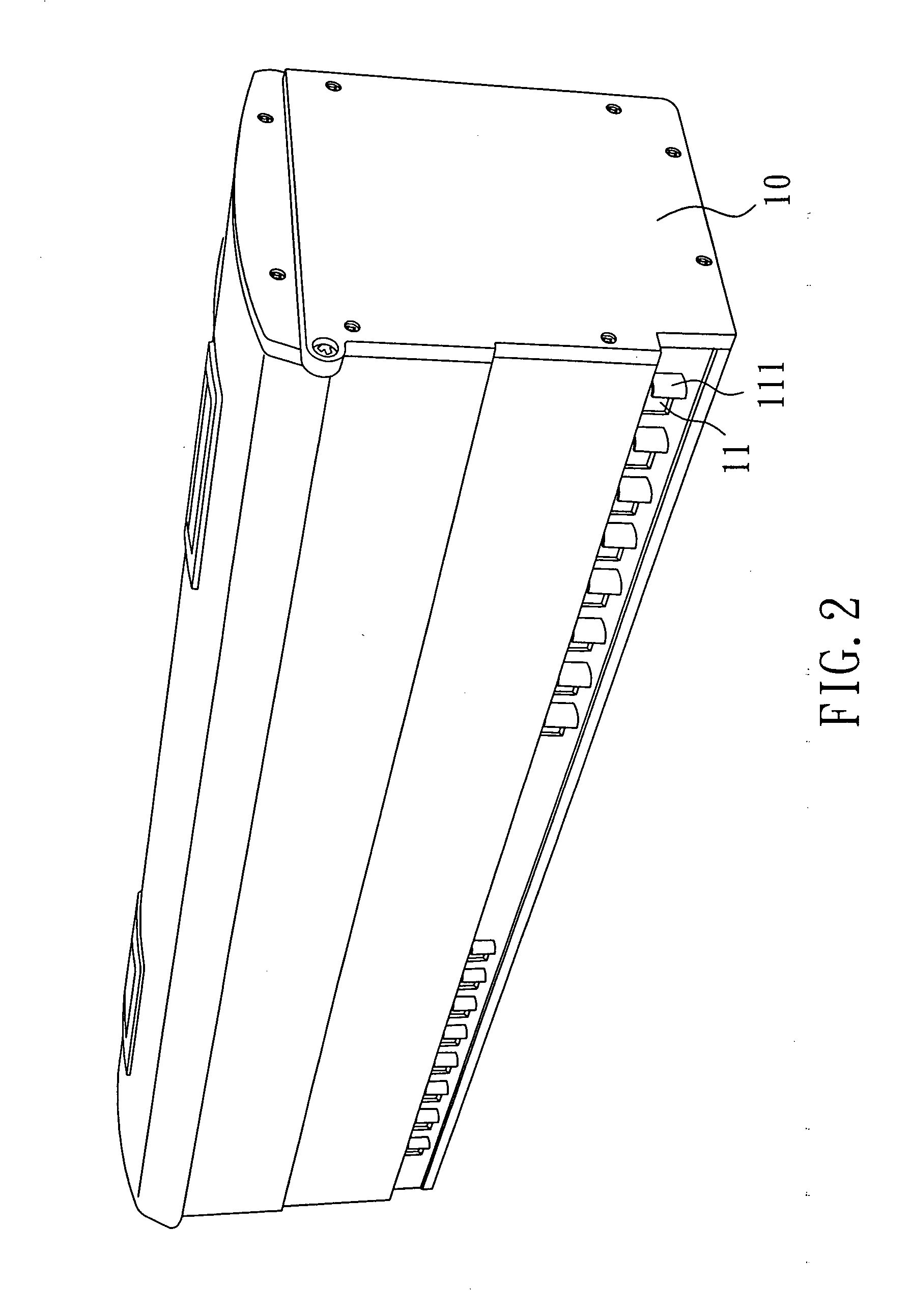
[0017] Referring to FIG. 1˜3, an air cleaner in accordance with the present invention is shown comprising a housing 10. According to the present preferred embodiment, the housing 10 is a rectangular case made out of metal, for example, aluminum, iron, or stainless steel. The housing 10 has an air inlet 11 (see FIG. 2) and an air outlet 12 (see FIG. 1) for letting air pass in and out of the housing 10, and louvers 111 adapted to close/open the air inlet 11 (see FIG. 2).
[0018] Further, a casing 20 is mounted inside the housing 10 and fixedly secured to the inside wall of the housing 10 by screws (see FIG. 5). As shown in FIGS. 3 and 5, the casing 20 has coupling grooves 21 bilaterally arranged in parallel at the bottom open side thereof at different elevation adapted to hold a first filter element 40 and a second filter element 50 corresponding to the air inlet 11 of the housing 10. The first filter element 40 is disposed in proximity to the air inlet 11 of the housing 10, comprising a rectangular filter frame 41, a plurality of partition ribs 42 connected between two opposite sides of the rectangular filter frame 41 and dividing the holding area of the rectangular filter frame 41 into separated open spaces, and wire gauzes 43 respectively suspended in the open spaces within the rectangular filter frame 41. The second filter element 50 is spaced above the first filter element 40, comprising a rectangular filter frame 51, a plurality of partition ribs 52 connected between two opposite sides of the rectangular filter frame 51 and dividing the holding area of the rectangular filter frame 51 into separated open spaces 53 which are mounted with filter sponges, active carbons, or sterilizing materials (see FIG. 3).
[0019] Further, two electric fans 30 are respectively affixed to the two distal ends of the casing 20. Two air ducts 31 are respectively coupled to the electric fans 30 and adapted to guide currents of air from the electric fans 30 to the air outlet 12 of the housing 10. The first filter element 40 removes solid matters from the currents of air that are drawn by the electric fans 30 and flow through the air inlet 11 into the inside of the casing 20. The second filter element 50 removes germs from the currents of air that are filtered through the first filter element 40. The air ducts 31 guide the well-filtered intake flow of air to the outside of the housing 10 through the air outlet 12. Therefore, the air cleaner supplies fresh clean air.
[0020] Further, a negative ion generator 70 and an UV (Ultraviolet) lamp 80 are mounted inside the casing 20. The negative ion generator 70 generates negative ions to remove dust from air passing through the casing 20 toward the air ducts 31 and the air outlet 12. The UV lamp 80 emits ultraviolet light to kill germs.
[0021] Further, a sound absorbing member 60, for example, a sound absorbing sponge is sandwiched between the outside wall of the casing 20 and the inside wall of the housing 10 to absorb sound, preventing noises.
[0022] Referring to FIGS. 3˜5 and FIG. 1, when in use, the electric fans 30 are started to draw currents of air through the air inlet 11 into the inside of the housing 10. At this time, the louvers 111 are set in a tilting position to stop outside moisture from entering the air inlet 11. The currents of air that flow through the air inlet 11 into the inside of the housing 10 are filtered by the first filter element 40 and the second filter element 50, preventing adhering of dust to the electric fans 30. By means of the effect of the electric fans 30 and the effect of the air dusts 31, the intake currents of air are guided out of the housing 10 through the air outlet 12 via the negative ion generator 70 and the UV lamp 80. Therefore, cleaned and sterilized currents of air are supplied to the desired space area. Further, because the housing 10 is made out of aluminum, the heat energy produced during operation of the electric fans 30 can be quickly dissipated out of the air cleaner.
[0023] Although a particular embodiment of the invention has been described in detail for purposes of illustration, various modifications and enhancements may be made without departing from the spirit and scope of the invention.

PUM

PropertyMeasurementUnit
Current
tensileMPa
Particle sizePa
strength10

Description & Claims & Application Information

We can also present the details of the Description, Claims and Application information to help users get a comprehensive understanding of the technical details of the patent, such as background art, summary of invention, brief description of drawings, description of embodiments, and other original content. On the other hand, users can also determine the specific scope of protection of the technology through the list of claims; as well as understand the changes in the life cycle of the technology with the presentation of the patent timeline. Login to view more.

Similar technology patents

Battery module

Owner:SK ON CO LTD

Thermosiphon for laptop computer

InactiveUS20080236788A1Efficiently dissipate heatEfficiently partitionDigital data processing detailsSemiconductor/solid-state device detailsLaptopEngineering
Owner:COOLIT SYSTEMS INC

Illuminator with a radiator

ActiveUS20210116121A1Efficiently dissipate heatPlanar light sourcesElongate light sourcesPhysicsEngineering
Owner:CHANGZHOU KAISEN PHOTOELECTRICITY CO LTD +1

Classification and recommendation of technical efficacy words

  • Absorb noise
  • Efficiently dissipate heat

Reactive Orthotropic Lattice Diffuser for Noise Reduction

ActiveUS20150259060A1Reduce amountAbsorb noiseBoundary layer controlsWing lift eficiencyFluid fieldEngineering
Owner:NASA

Automatic power-off socket used for computer

InactiveCN109873266AAbsorb noiseTimely releaseCoupling contact membersPolyesterEngineering
Owner:谷合龙

Device having improved heat dissipation

InactiveUS20050117304A1Efficiently dissipate heatStatic indicating devicesInstrumental cooling apparatusOperating temperatureSurface plate
Owner:SAMSUNG SDI CO LTD

LED illumination device

Owner:PYROSWIFT HOLDING CO LIMITED

Heat-dissipating assembly structure

InactiveUS20080101035A1Efficiently dissipate heatEasily and rapidly be assemble and instalSemiconductor/solid-state device detailsSolid-state devicesHeat sinkEngineering
Owner:CHEN CHIUNG YI
Why Eureka
Try Eureka