Estimation of head-related transfer functions for spatial sound representation

a transfer function and spatial sound technology, applied in the field of sound reproduction, can solve the problems of inability to distinguish between different virtual sources of sounds, appreciable errors can occur, and limited spatial characteristics of sounds perceived by users

Inactive Publication Date: 2006-03-30
INTERVAL RESEARCH CORPORATION
View PDF5 Cites 66 Cited by
  • Summary
  • Abstract
  • Description
  • Claims
  • Application Information

AI Technical Summary

Problems solved by technology

In most of these situations, the sounds perceived by the user have limited spatial characteristics.
Typically, the user is able to distinguish between two dipolar sources, e.g. left and right balance, but is otherwise unable to distinguish between different virtual sources of sounds that are theoretically located at a variety of different positions, relative to the user.
As a result, the HRTF is sufficiently unique to an individual that appreciable errors can occur if one person listens to sound that is synthesized or filtered in accordance with a different person's HRTF.
For further information regarding the measurement of an HRTF, see Blauert, J., Spatial Hearing, MIT Press, 1983, particularly at Section 2.2, the disclosure of which is incorporated herein by reference While this direct measurement approach may be feasible for a limited number of users, it will be appreciated that it is not practical for applications designed to be used by a large number of listeners.
These attempts to characterize the HRTF have met with limited success, since they only provide a rough basis for an estimation model, but do not actually couple characteristics of the listener to his or her HRTF.
Consequently, the principle components analysis does not provide a mechanism to find the best HRTF for a given user.
While this approach appears to provide more accurate results, the need to obtain the necessary physical measurements can be inconvenient and time consuming, and therefore may not be practical in all situations.
In addition, the physical principles that determine the HRTF are not all known, and therefore the model may not be truly representative.

Method used


Image

  • Estimation of head-related transfer functions for spatial sound representation
  • Estimation of head-related transfer functions for spatial sound representation
  • Estimation of head-related transfer functions for spatial sound representation

Examples


Embodiment Construction

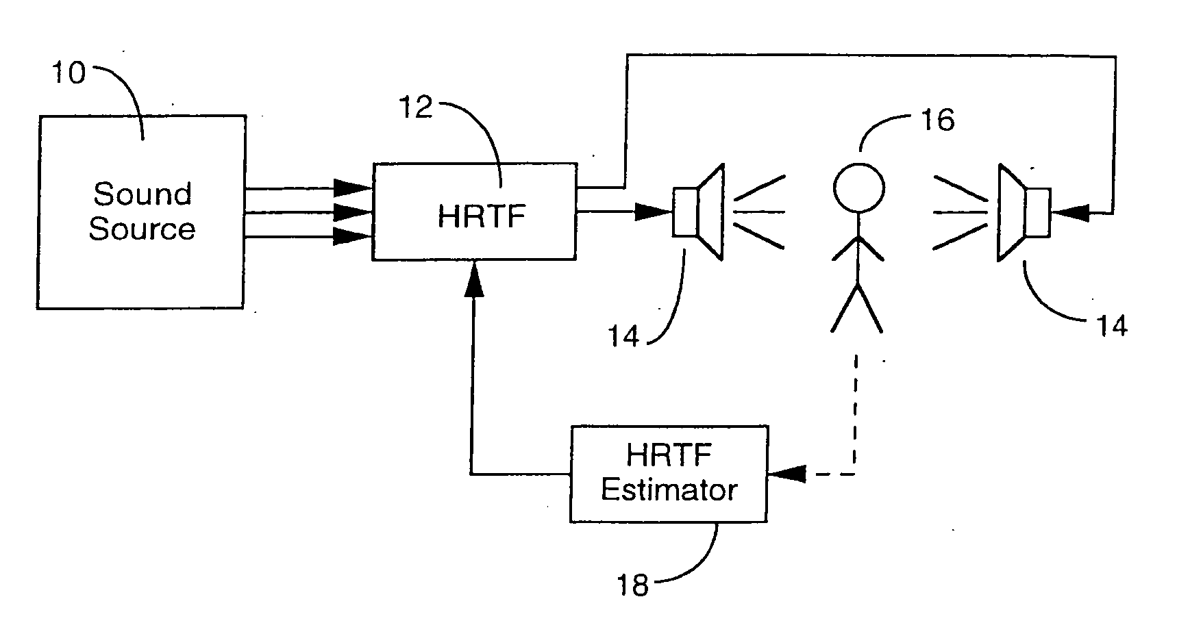
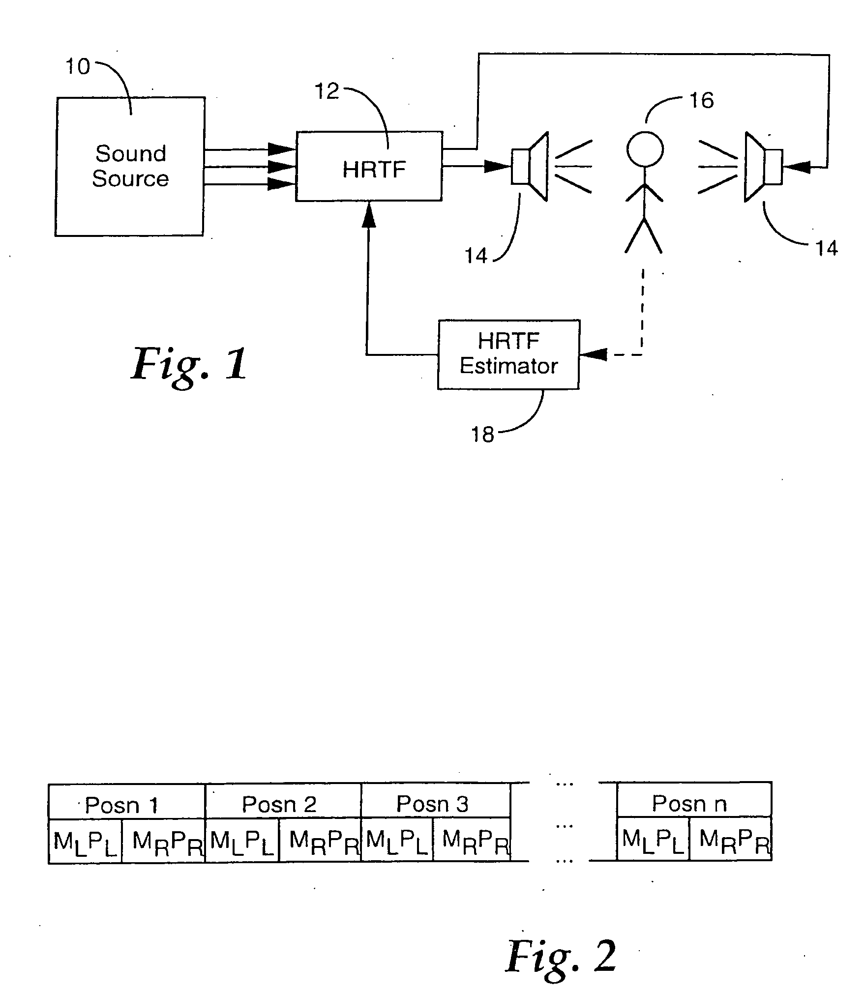
[0016] Generally speaking, the present invention is directed to the estimation of an HRTF for a particular listener, based upon information that is available about physical characteristics of that listener. Once it has been determined, the HRTF can be used to generate spatial sound that is tuned to that listener's auditory response characteristics, so that the listener is able to readily identify and distinguish between sounds that appear to come from spatially diverse locations. An example of a system which employs the HRTF for such a purpose is schematically illustrated in FIG. 1. Referring thereto, various sounds that are respectively associated with different locations in a virtual environment are generated by a sound source 10, such as a synthesizer, a microphone, a prerecorded audio file, etc. These sounds are transformed in accordance with an HRTF 12, and applied to two or more audio output devices 14, such as speakers, headphones, or the like, to be heard by a listener 16. T...


PUM


Abstract

The estimation of an HRTF for a given individual is accomplished by means of a coupled model, which identifies the dependencies between one or more images of readily observable characteristics of an individual, and the HRTF that is applicable to that individual. Since the HRTF is highly influenced by the shape of the listener's outer ear, as well as the shape of the listener's head, images of a listener which provides this type of information are preferably applied as an input to the coupled model. In addition, dimensional measurements of the listener can be applied to the model. In return, the model provides an estimate of the HRTF for the observed characteristics of the listener.

Description

CROSS REFERENCE TO OTHER APPLICATIONS [0001] This application is a continuation of co-pending U.S. patent application Ser. No. 09 / 369,340, entitled ESTIMATION OF HEAD-RELATED TRANSFER FUNCTIONS FOR SPATIAL SOUND REPRESENTATION filed Aug. 6, 1999 which is incorporated herein by reference for all purposes, which claims priority to U.S. Provisional Application No. 60 / 095,442, entitled ESTIMATION OF HEAD-RELATED TRANSFER FUNCTIONS FOR SPATIAL SOUND REPRESENTATION filed Aug. 6, 1998 which is incorporated herein by reference for all purposes. FIELD OF THE INVENTION [0002] The present invention is generally directed to the reproduction of sounds, and more particularly to the estimation of head-related transfer functions for the presentation of three-dimensional sound. BACKGROUND OF THE INVENTION [0003] Sound is gaining increasing interest as an element of user interfaces in a variety of different environments. Examples of the various uses of sound include human / computer interfaces, auditor...

Claims


Application Information

Patent Timeline
Patent Type & Authority Applications(United States)
IPC IPC(8): H04R5/02
CPCH04S2420/01H04S1/002H04S7/301
Inventor SLANEY, MALCOLMCOVELL, MICHELESAUNDERS, STEVEN E.
Owner INTERVAL RESEARCH CORPORATION
Why Eureka
Try Eureka