Splice holder device

a technology of splice and holder, which is applied in the direction of instruments, optical light guides, optics, etc., can solve the problem of not being generally suitable for use with fiber optic cables

Active Publication Date: 2006-03-30
CORNING RES & DEV CORP
View PDF34 Cites 46 Cited by
  • Summary
  • Abstract
  • Description
  • Claims
  • Application Information

AI Technical Summary

Benefits of technology

[0016] The above summary of the present invention is not intended to describe each illustrated embodiment or every implementatio

Problems solved by technology

Conventional enclosures are typically intended for use with electrically conductive telecommunications cables, and are not generally su

Method used


Image

  • Splice holder device
  • Splice holder device
  • Splice holder device

Examples


Embodiment Construction

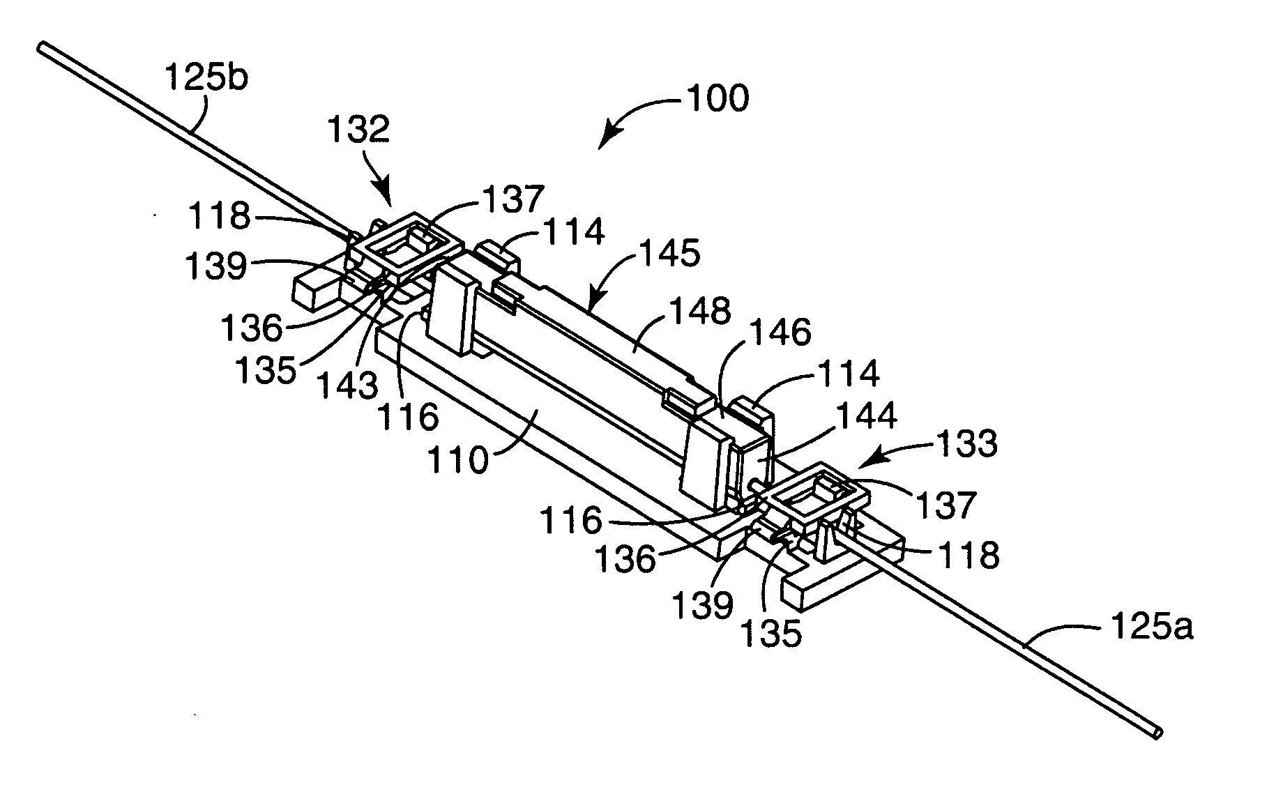
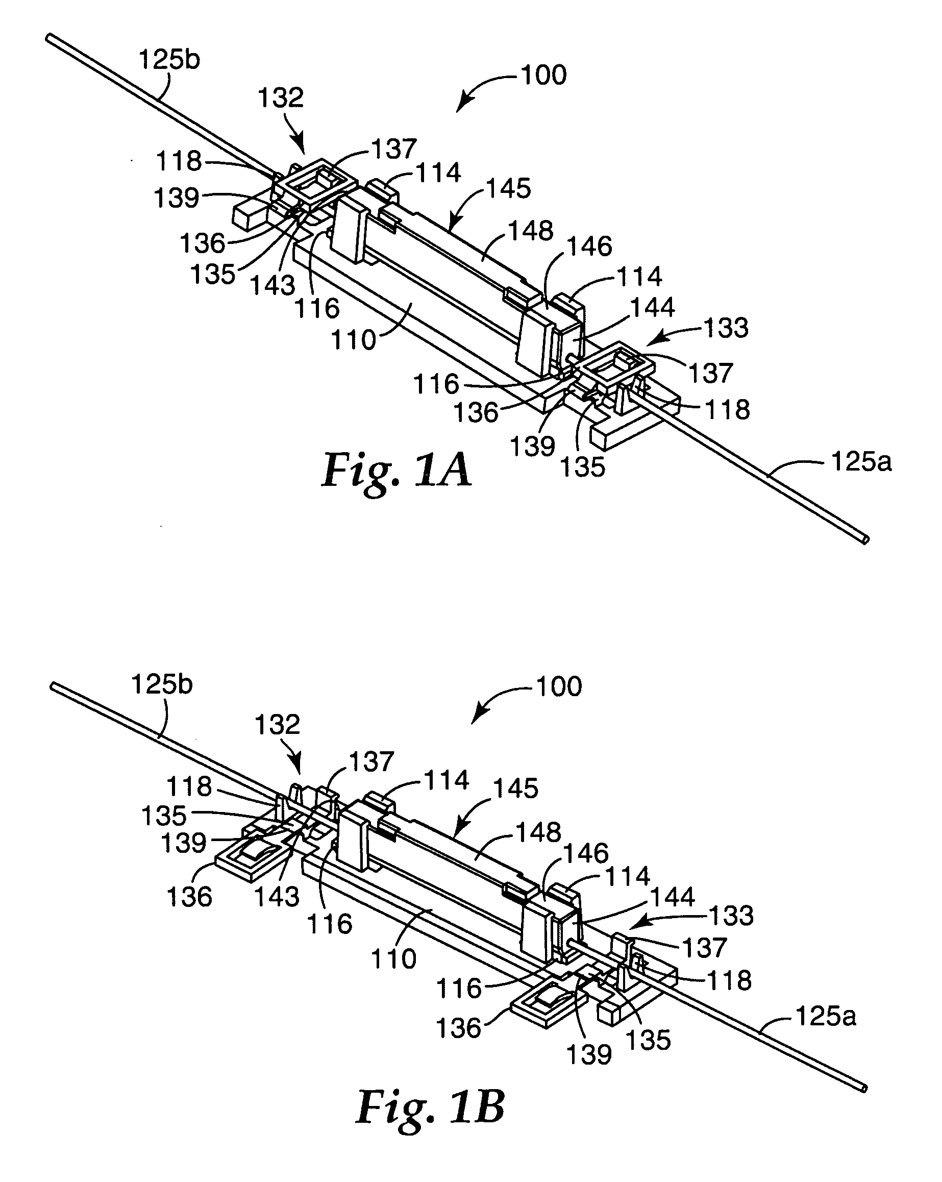
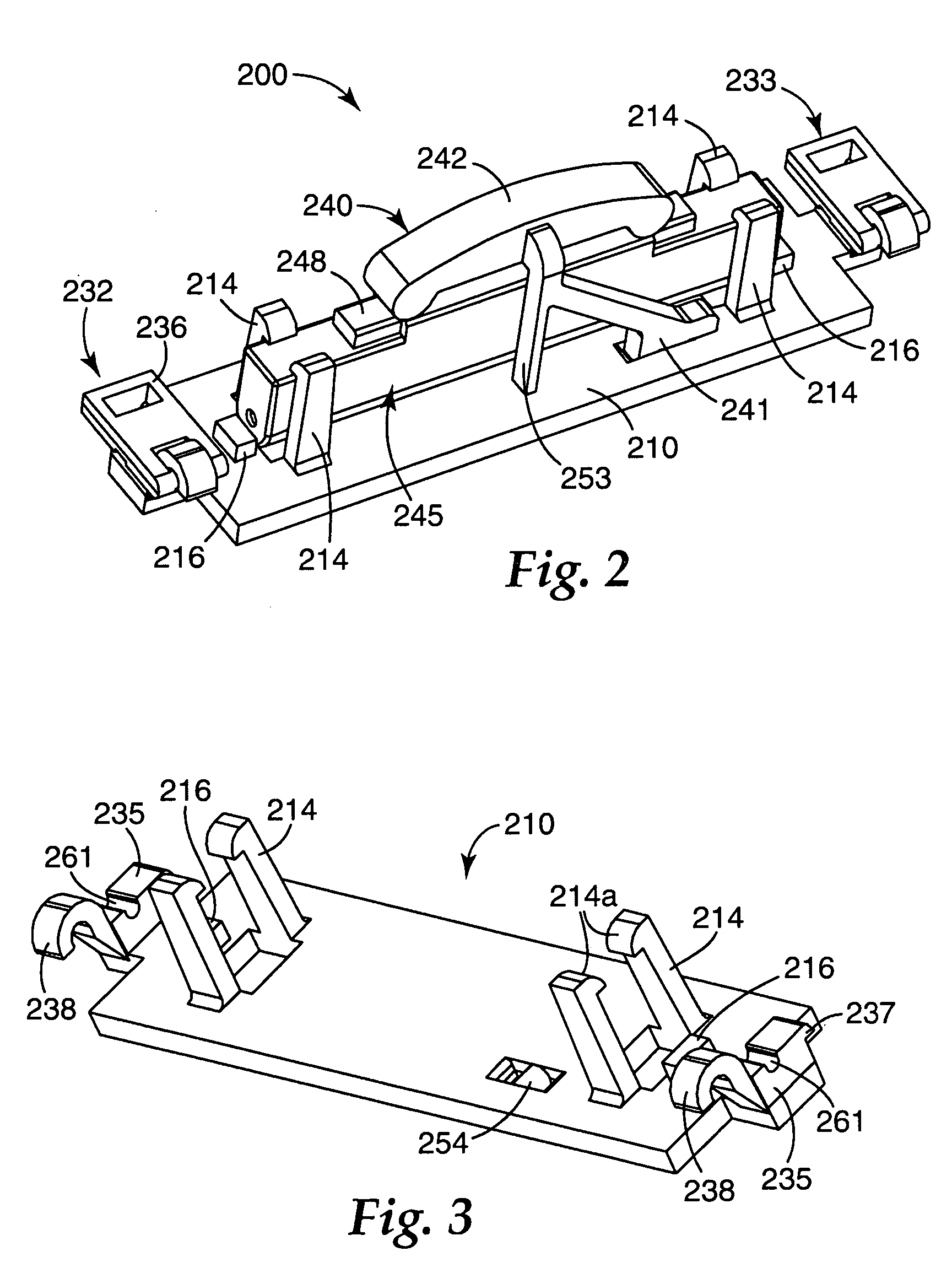
[0036] In the following Detailed Description, reference is made to the accompanying drawings, which form a part hereof, and in which is shown by way of illustration specific embodiments in which the invention may be practiced. In this regard, directional terminology, such as “top,”“bottom,”“front,”“back,”“leading,”“trailing,” etc., is used with reference to the orientation of the Figure(s) being described. Because components of embodiments of the present invention can be positioned in a number of different orientations, the directional terminology is used for purposes of illustration and is in no way limiting. It is to be understood that other embodiments may be utilized and structural or logical changes may be made without departing from the scope of the present invention. The following detailed description, therefore, is not to be taken in a limiting sense, and the scope of the present invention is defined by the appended claims.

[0037] Embodiments of the present invention are dir...


PUM


Abstract

A splice holder device includes a tray mountable in a telecommunications closure, the tray including a splice mounting mechanism configured to receive a splice device. The splice holder device also includes first and second fiber clamps disposed on the tray, wherein the first and second fiber clamps are each configured to releasably secure a buffered portion of an optical fiber. The tray can include a single splice device, such as a mechanical splice, mounted therein or can include a plurality of splice devices mounted therein. The splice holder device can be configured to be securedly mounted in a telecommunications enclosure.

Description

RELATED APPLICATIONS [0001] The present application claims the benefit of priority of U.S. Provisional Patent Application No. 60 / 613,169 (filed Sep. 24, 2004) and 60 / 691,881 (filed Jun. 17, 2005), both of which are incorporated by reference herein in their entirety.BACKGROUND OF THE INVENTION [0002] 1. Field of the Invention [0003] The present invention is directed to a splice holder device for telecommunication terminals and closures. [0004] 2. Related Art [0005] Telecommunication cables are used for distributing data across vast networks. The majority of telecommunication cables are electrically conductive cables (typically copper), although the use of optical fiber cables is growing rapidly as larger and larger amounts of data are transmitted. As telecommunication cables are routed across networks, it is necessary to periodically open the cable and splice or tap into the cable so that data may be distributed to “branches” of the network. The branches may be further distributed un...

Claims


Application Information

Patent Timeline
IPC IPC(8): G02B6/00G02B6/255
CPCG02B6/3801G02B6/4471G02B6/3802G02B6/255
Inventor CARPENTER, JAMES B.HILLS, DOUGLAS P.PARK, CHANSOOLLARSON, DONALD K.WINBERG, PAUL N.
Owner CORNING RES & DEV CORP
Why Eureka
Try Eureka