Tripod type constant-velocity joint and image-forming device

Active Publication Date: 2006-03-30
NTN CORP
View PDF6 Cites 74 Cited by
  • Summary
  • Abstract
  • Description
  • Claims
  • Application Information

AI Technical Summary

Benefits of technology

[0024] By rotating the photoconductor drum at a constant speed, it is possible to prevent shrinkage or expansion of any electrostatic latent image formed on the photoconductor drum, and also to prevent any toner image on the photoconductor drum from shrinking or expanding when it is transferred onto the transfer material A

Problems solved by technology

Thus, although such a joint is high in strength, it is heavy, needs lubrication with grease, and tends to produce loud noise.
Its use is thus limited.
For example, such a joint is not suitable for use in office machines, audio devices, medical instruments, food producing machines, household appliances, etc.
This increases the number of parts of the joint and thus its size, and pushes up its cost, too.
Although this publication proposes to arrange the exposure

Method used


Image

  • Tripod type constant-velocity joint and image-forming device
  • Tripod type constant-velocity joint and image-forming device
  • Tripod type constant-velocity joint and image-forming device

Examples


Example

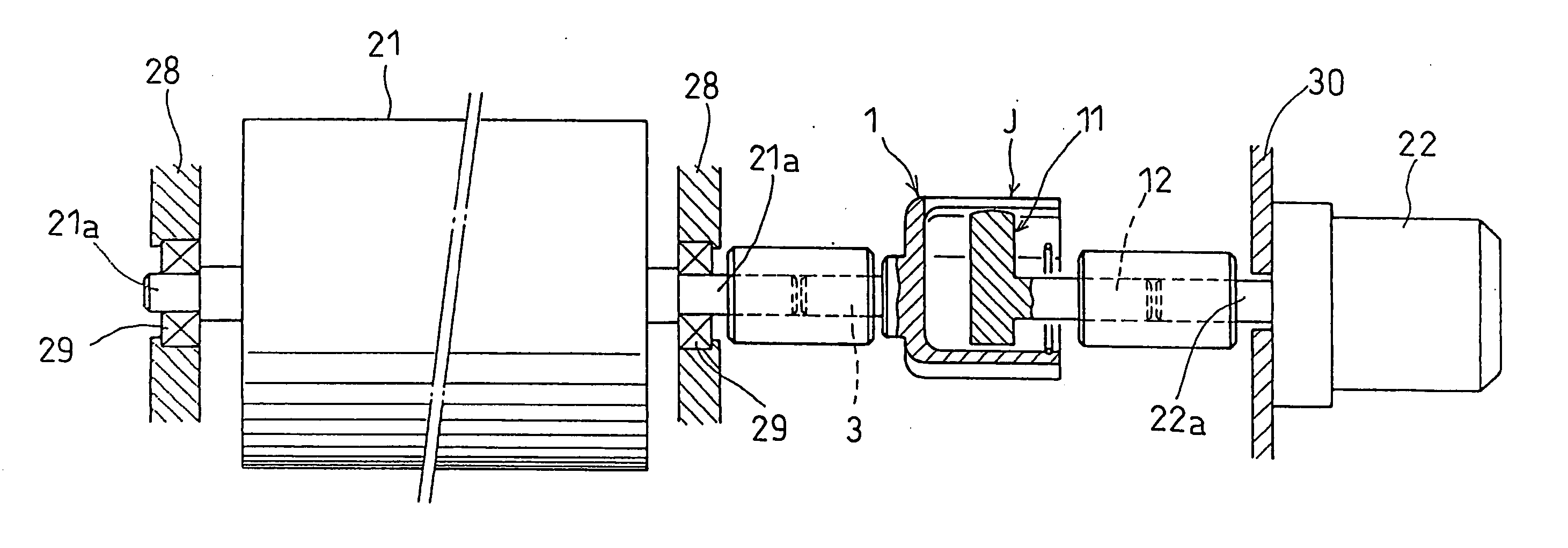
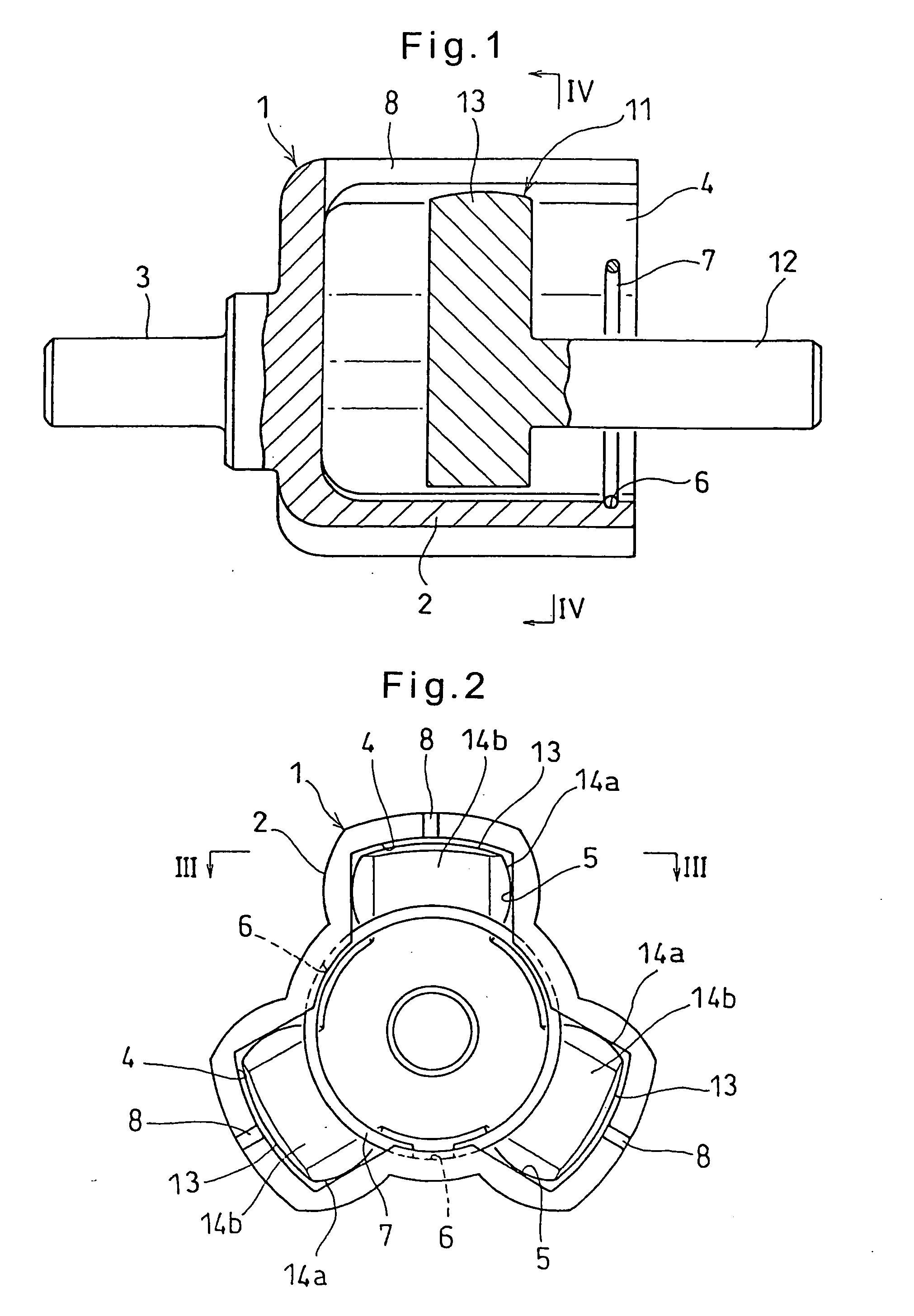
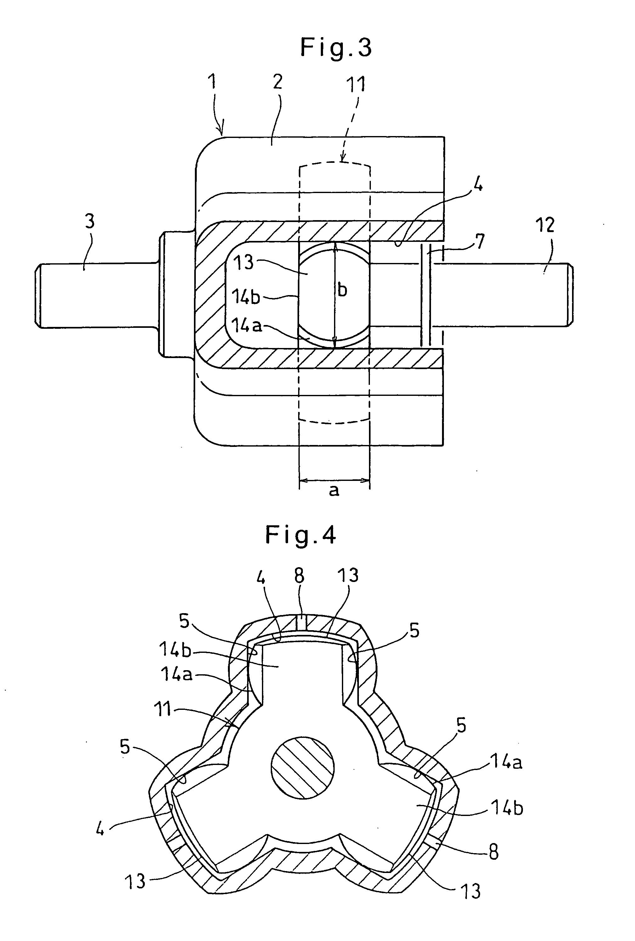
[0033] The embodiment of the present invention is now described with reference to the drawings. As shown in FIGS. 1 to 4, the tripod type constant-velocity joint according to the present invention comprises an outer ring 1 and a tripod member 11 inserted in the outer ring 1.

[0034] The outer ring 1 includes a cup 2 having an opening at one end, and an end wall closing the other end thereof. A first shaft 3 is integrally formed on the outer surface of the end wall of the cup 2. Three track grooves 4 are formed in the inner surface of the outer ring 1 so as to axially extend from the open end of the cup 2 and so as to be circumferentially spaced apart from each other at equal intervals of 120 degrees. Each track groove 4 has a pair of circumferentially opposed, flat side faces 5 that extend parallel to each other.

[0035] The tripod member 11 carries a second shaft 12 and is integrally provided with three protrusions 13 inserted in the respective track grooves 4 of the outer ring 1.

[0...


PUM


Abstract

A tripod type constant-velocity joint includes an outer ring formed with three axially extending track grooves circumferentially spaced apart from each other by 120 degrees. Each track groove has a pair of opposed, axially extending side faces. A tripod member is inserted in the outer ring. The tripod member includes three protrusions each slidably received in one of the track grooves and having a pair of circumferentially curved side faces each opposing one of the pair of side faces of each track groove. Torque is thus transmitted between the outer ring and the tripod member. At least the protrusions of the tripod member are formed of a synthetic resin.

Description

BACKGROUND OF THE INVENTION [0001] The present invention relates to a tripod type constant-velocity joint through which a driving shaft and a driven shaft are coupled together so as to transmit torque from the driving shaft to the driven shaft, and an image forming device including such a tripod type constant-velocity joint. [0002] A constant-velocity joint is typically used to transmit torque from a vehicle drive shaft to an axle. [0003] Through such a constant-velocity joint, torque can be transmitted from a driving shaft to a driven shaft such that the driven shaft is rotated K at a constant speed even if the angle between the driving shaft and the driven shaft varies. Thus, constant-velocity joints are used in various industrial machines other than motor vehicles, too. [0004] There are known two types of constant-velocity joints, i.e. fixed type constant-velocity joints, which only allow the driving and driven shafts to incline relative to each other, and sliding type constant-v...

Claims


Application Information

Patent Timeline
IPC IPC(8): G03G15/00
CPCG03G15/757
Inventor YAMAZAKI, MASAYUKIFUKUZAWA, SATORUOHASHI, MASAAKIKOBAYASHI, SHIGEO
Owner NTN CORP
Why Eureka
Try Eureka