Exhaust gas purification system

Active Publication Date: 2015-09-22
YANMAR POWER TECHNOLOGY CO LTD
View PDF8 Cites 3 Cited by
  • Summary
  • Abstract
  • Description
  • Claims
  • Application Information

AI Technical Summary

Benefits of technology

[0030]According to the invention of the seventh aspect, since in the case that the current rotating speed and torque in the engine are greater than the upper limit threshold values, the rotating speed and the torque of the engine are lowered little by little to the upper limit threshold values under the execution of the limp home mode, it is possible to prevent the rotating speed and the torque from being rapidly changed (lowered) in the case that the mode is changed to the limp home mode. Accordingly, it is possible to achieve an effect of avoiding a problem that the operator can not deal and an engine stall is caused, by doing away with an uncomfortable feeling of the operator at the time of execution of the limp home mode.
[0031]According to the invention of the eighth aspect, since the exhaust gas purification system includes the abnormally high temperature informing means which is actuated in the case that the temperature of the exhaust gas within the exhaust gas purification device is equal to or higher than the abnormal temperature, it is possible to achieve an effect of informing the operator of the exhaust gas temperature abnormality (the runaway combustion) on the basis of the information of the abnormally high temperature informing means, thereby contributing to the prevention of expansion in the damage such as the melting of the exhaust gas purification device.
[0032]According to the invention of the ninth aspect, since the exhaust gas purification system includes the renewal advance notifying means which is actuated in the case that the clogged state of the exhaust gas purification device becomes equal to or more than the prescribed level, and the renewal admittance input means which allows the actuation of the renewing device, and the auxiliary renewing mode or the forced renewing mode is executed when the allowing operation of the renewal admittance input means is carried out under actuation of the renewal advance notifying means, it is possible to inhibit the renewing motion of the exhaust gas purification device by not carrying out the allowing operation of the renewal admittance input means. In other words, it is possible to inhibit the renewing motion of the exhaust gas purification device on the basis of an inte

Problems solved by technology

Accordingly, in an engine with a DPF, even if a DPF renewing motion is executed by rising an exhaust gas temperature, there may be a case that a DPF purifying capacity is not sufficiently recovered (a case that the renewal is not sufficient).
However, in an aspect that the fuel is supplied into the DPF by the post injection so as to positively burn the PM, there has been a problem that a fuel consumption is widely deteriorated in the case that a frequency of the post injection is high (the number of times is increased), and an unburnt fuel stays within each of cylinders of the en

Method used


Image

  • Exhaust gas purification system
  • Exhaust gas purification system
  • Exhaust gas purification system

Examples


Example

(1) Structure of Engine and Periphery of the Same in First Embodiment

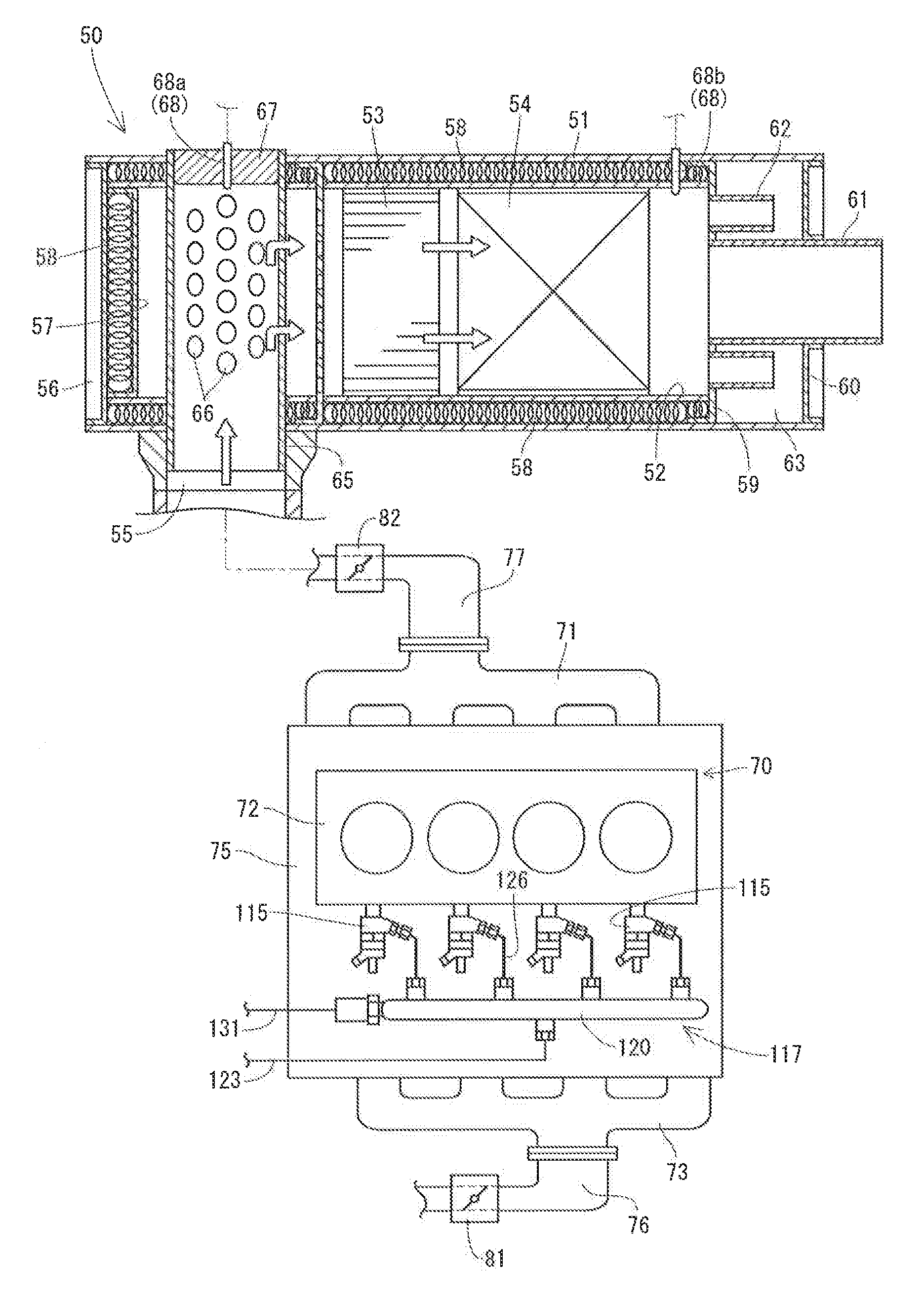
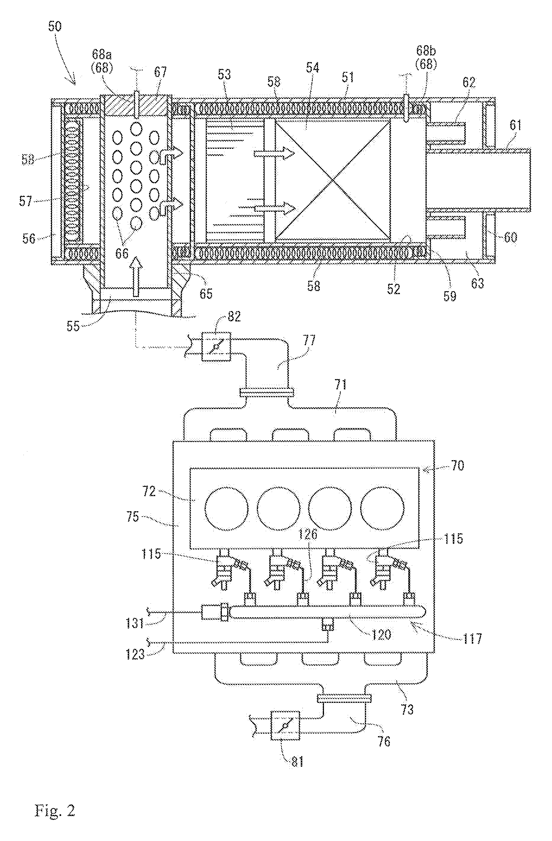
[0050]FIG. 1 to FIG. 8 show a first embodiment of the present invention. First of all, a description will be given of a structure of an engine 70 and a periphery of the same with reference to FIG. 1 and FIG. 2. As shown in FIG. 2, the engine 70 is a four-cylinder type diesel engine, and is provided in an upper face with a cylinder block 75 to which a cylinder head 72 is fastened. An intake manifold 73 is connected to one side face of the cylinder head 72, and an exhaust manifold 71 is connected to the other side face. A common rail system 117 which supplies a fuel to each of cylinders of the engine 70 is provided below the intake manifold 73 in a side face of the cylinder block 75. An intake air throttle device 81 for regulating an intake air pressure (an amount of intake air) of the engine 70 and an air cleaner (not shown) are connected to an intake pipe 76 which is connected to an air intake upstream side of the ...

Example

[0116]FIG. 9 to FIG. 13 show a second embodiment of the present invention. The second embodiment is different from the first embodiment in a point that a renewing switch 221 which selects whether the renewing motion of the DPF 50, is employed as the renewal admittance input means, in place of the emergency switch 21, and a point that the renewal inhibition button 27 and the renewal inhibition lamp 28 are omitted, however, basically has the same structure as the first embodiment. A description will be mainly given below of the different points from the first embodiment.

[0117]The renewing switch 221 shown in FIG. 9 and FIG. 10 belongs to an alternate motion type. In other words, the renewing switch 221 is a lock type push switch which is locked at a push-down position by one push-down motion, and is returned to the original position by one more push-down motion. If the renewing switch 221 is locked at the pushdown position at the time of blinking of the renewal lamp 24 which informs o...


PUM


Abstract

An exhaust gas purification device is arranged in an exhaust gas route of a common rail type engine. At least one of an intake air throttle device and an exhaust gas throttle device are arranged in intake and exhaust systems of the engine. In the case that a clogged state of the exhaust gas purification device becomes equal to or more than a prescribed level, an auxiliary renewing mode which raises the temperature of an exhaust gas from the engine by actuating at least one of the intake air throttle device and the exhaust gas throttle device is executed, and in the case that the clogged state of the exhaust gas purification device is not improved even by executing the auxiliary renewing mode, a forced renewing mode which supplies a fuel into the exhaust gas purification device by a post injection is executed.

Description

BACKGROUND OF THE INVENTION[0001]The present invention relates to an exhaust gas purification system with respect to an engine which is mounted to a working machine, for example, a construction machine, an agricultural machine and an engine generator.[0002]In recent years, as an application of an emission control of a high order with regard to a diesel engine (hereinafter, refer simply to as an engine), it is going to be desired to mount an exhaust gas purification device which purifies an air pollutant in an exhaust gas, to a construction machine, an agricultural machine and an engine generator to which the engine is mounted. As the exhaust gas purification device, a diesel particulate filter (hereinafter, refer to as DPF) has been known (refer to Patent Documents 1 and 2). The DPF is provided for collecting a particulate matter (hereinafter, refer to as PM) or the like. In this case, if the PM which is collected by the DPF exceeds a prescribed amount, a distribution resistance wit...

Claims


Application Information

Patent Timeline
IPC IPC(8): F01N3/00F01N3/023F01N9/00F01N3/035F02D41/02F02D41/14F02D41/22
CPCF01N3/023F01N3/0235F01N9/002F02D41/029F01N3/035F01N2240/36F02D41/0245F02D41/1446F02D2041/227F02D2041/228Y02T10/47F02D2041/0265Y02T10/40F01N3/00F01N3/02F02D43/00F02D45/00
Inventor NOMA, YASUOTOGASHI, TAICHIFUKUDA, TOMOHIROOHTA, ATSUSHIJOUNOUCHI, KATSUNARI
Owner YANMAR POWER TECHNOLOGY CO LTD
Why Eureka
Try Eureka