Method and apparatus for laser drilling

Inactive Publication Date: 2006-04-13
HITACHI SEIKO LTD
View PDF2 Cites 5 Cited by
  • Summary
  • Abstract
  • Description
  • Claims
  • Application Information

AI Technical Summary

Benefits of technology

[0009] It is an object of the invention to provide a laser drilling method that solves the above described problems of the related art, and prevents hanging or expansion of

Problems solved by technology

However, in the case of directly drilling a double-sided copper-clad film having a copper foil of 3 to 5 μm thick by a carbon dioxide laser, the copper foil is too thin to perform surface roughening that requires a roughness of at least 2 μm.
The experiments have also revealed that the uneven intensity distribution of the laser beam impractically causes the remainder of the copper foil to hang 3 just before the hole is completed through the copper foil, though this may also occur in a current 18-μm-thick copper foil regardless of the thickness of copper foil.
Further, the l

Method used


Image

  • Method and apparatus for laser drilling
  • Method and apparatus for laser drilling
  • Method and apparatus for laser drilling

Examples


Embodiment Construction

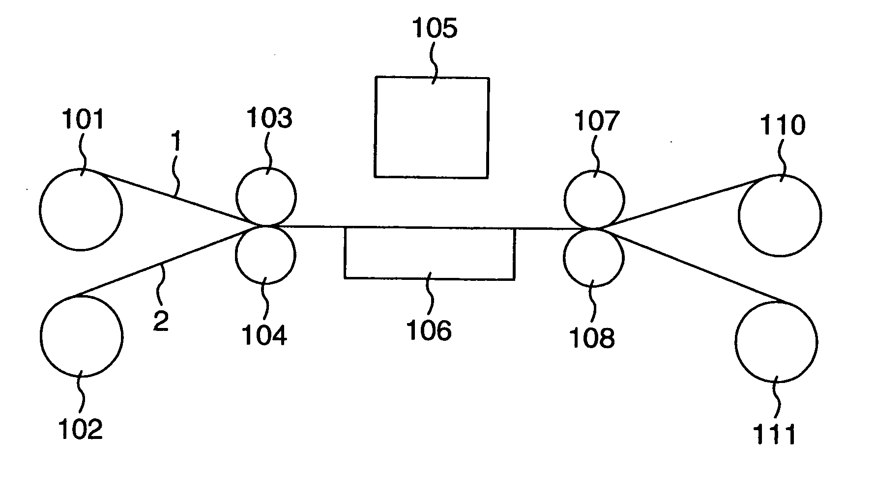
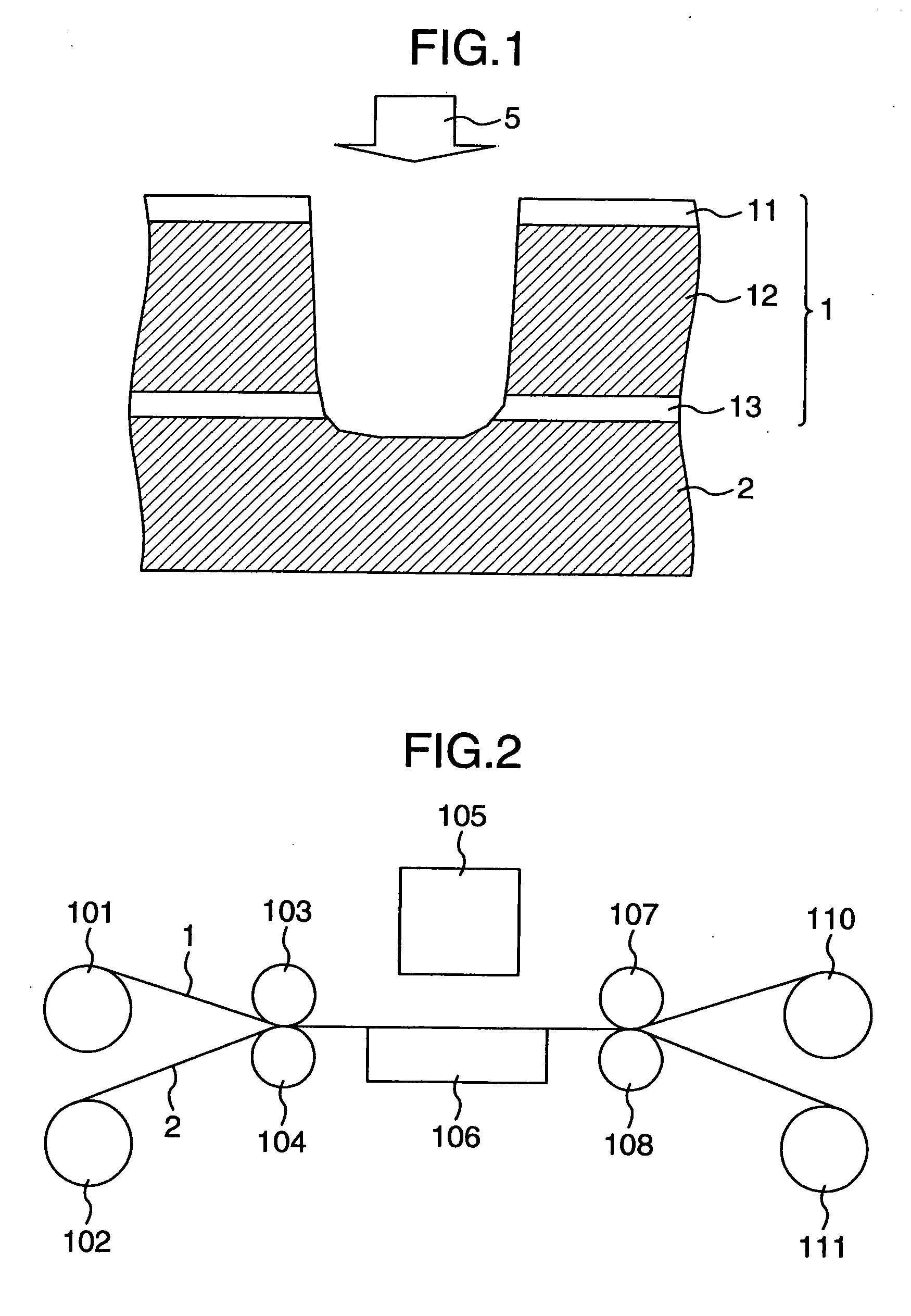
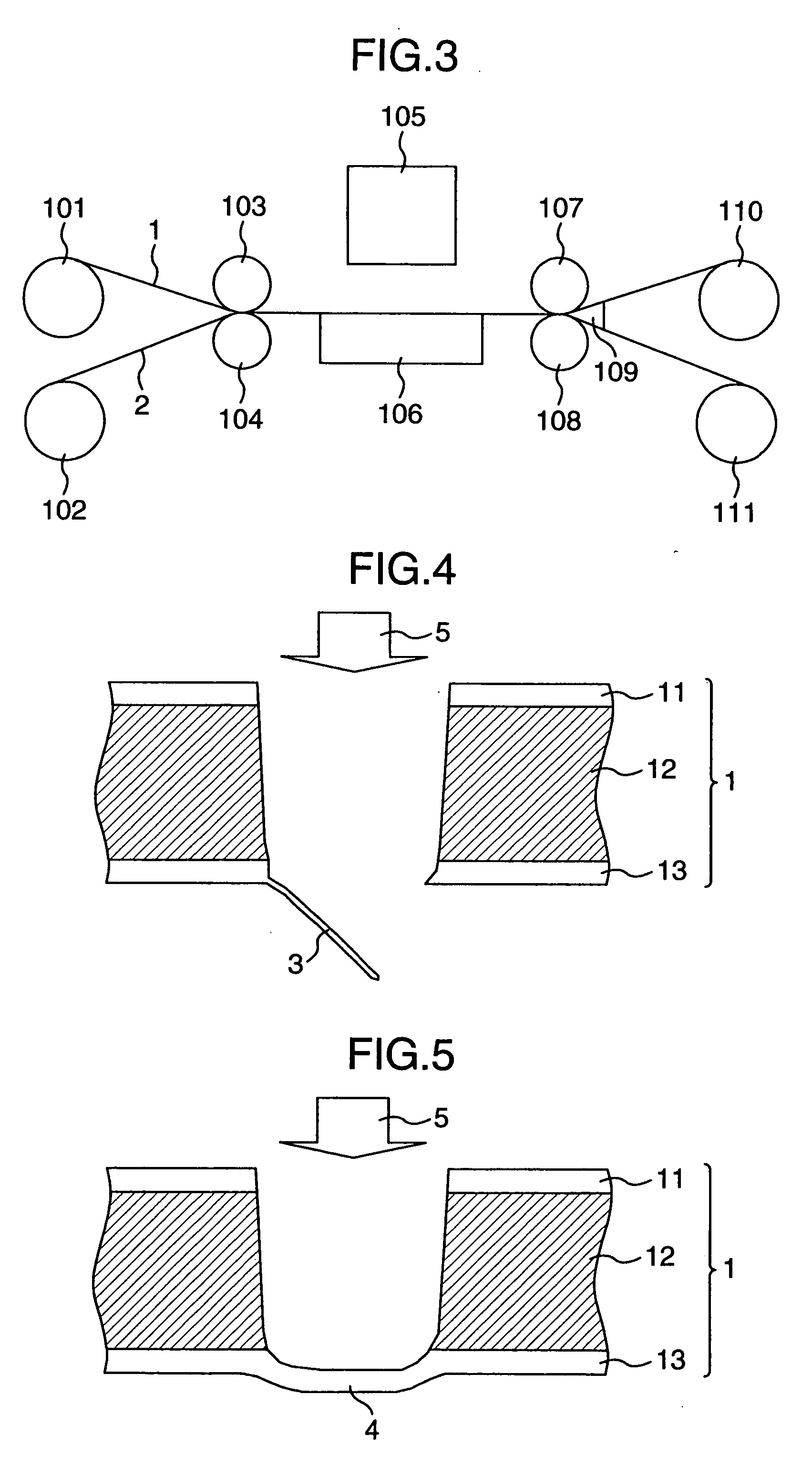
[0023] Now, an embodiment of the invention will be described with reference to the drawings. FIG. 1 is an illustration of a drilling method according to the invention. Here, reference numeral 1 denotes a double-sided copper-clad film (a width of 70 to 500 mm) consisting of copper foils 11 and 13 of 3 to 5 μm thick whose surfaces are not roughened, and a polyimide insulating resin film 12 of 25 to 30 μm thick. The copper foil 11 is not always necessary in the laser drilling method according to the invention, and the copper foil 13 having a current thickness of 18 μm or more is similarly processable. Reference numeral 2 denotes a resin film bonded to the backside thereof, and reference numeral 5 denotes an incident direction of an ultraviolet laser beam. A polyethylene based material is preferable as the resin film 2. The thickness of 25 μm or more is effective, and the thickness of 50 μm or more is more preferable in practical use. The example in FIG. 1 shows a through hole formed. T...


PUM

PropertyMeasurementUnit
Pressureaaaaaaaaaa
Expansion enthalpyaaaaaaaaaa

Abstract

There is provided a laser drilling method that prevents hanging, expansion, or crinkles of copper foil caused when an ultraviolet laser beam that requires no surface roughening is used for a thin double-sided copper-clad film. The drilling method of the copper-clad film comprises the steps of: using an ultraviolet laser as a laser beam; drilling after bonding a resin film to the backside of the film which is the opposite side to the laser-beam-incidence; and delaminating the resin film on the backside after drilling. The resin film bonded to the backside prevents the copper foil from hanging, thus allowing the laser beam to be efficiently applied to the copper foil, and allowing the copper foil to be completely removed by ablation. In the case of a blind hole, the resin film bonded to the backside prevents expansion of the copper foil. Crinkles can be also prevented.

Description

[0001] This application is a divisional application of Ser. No. 10 / 854,214, filed May 27, 2004.BACKGROUND OF THE INVENTION [0002] The present invention relates to a method of and an apparatus preferable for drilling an ultrathin flexible printed circuit board by a laser. RELATED ART [0003] Currently used as a flexible printed circuit board on which IC chips or the like are mounted is a double-sided copper-clad film having a polyimide film of about 100 μm thick and copper foils of about 18 μm thick bonded to both sides of the polyimide film. The thicknesses thereof are expected to be thinner, and there is a need for using an ultrathin double-sided copper-clad film having a polyimide film of about 25 to 30 μm thick used as an insulting resin film and copper foils of 3 to 5 μm thick bonded to both sides of the polyimide film. There is also a need for microholes having a diameter of 50 μm or less to be drilled in the film. [0004] As a method of drilling a double-sided copper-clad film u...

Claims


Application Information

Patent Timeline
IPC IPC(8): B23K26/38B23K26/382B23K26/18B23K101/42H05K1/00H05K3/00
CPCB23K26/0846Y10T156/19B23K26/381B23K2203/12H05K1/0393H05K3/0038H05K2201/0394H05K2203/0156H05K2203/1545B23K26/401B23K26/4065B23K26/409B23K26/4095Y10T156/1158B23K26/18B23K26/382B23K26/40B23K2101/35B23K2103/12B23K2103/172B23K2103/42B23K2103/50
Inventor ARAI, KUNIOISHII, KAZUHISA
Owner HITACHI SEIKO LTD
Why Eureka
Try Eureka