Connector

Active Publication Date: 2019-01-03
SUMITOMO WIRING SYST LTD
View PDF1 Cites 0 Cited by
  • Summary
  • Abstract
  • Description
  • Claims
  • Application Information

AI Technical Summary

Benefits of technology

[0007]Further, the contact of the opening restricting portion with the front end of the forward movement restricting portion prevents a forward positional deviation of the cover with respect to the housing. The opening restricting portion has both a function of preventing a positional deviation of the cover and a function of preventing the expansion of the cover. Thus, an entire configuration can be simplified as compared to the case where both functions are provided individually.
[0008]The forward movement restricting portion may be a rib extending along an opening edge of the wire pull-out opening. According to this configuration, the shape of the wire pull-out opening is maintained by the forward movem

Problems solved by technology

In the above case, an excessive stress is generated in the cover when the pulled-out wire is swung a large amount and both side walls of the co

Method used


Image

  • Connector
  • Connector
  • Connector

Examples


Example

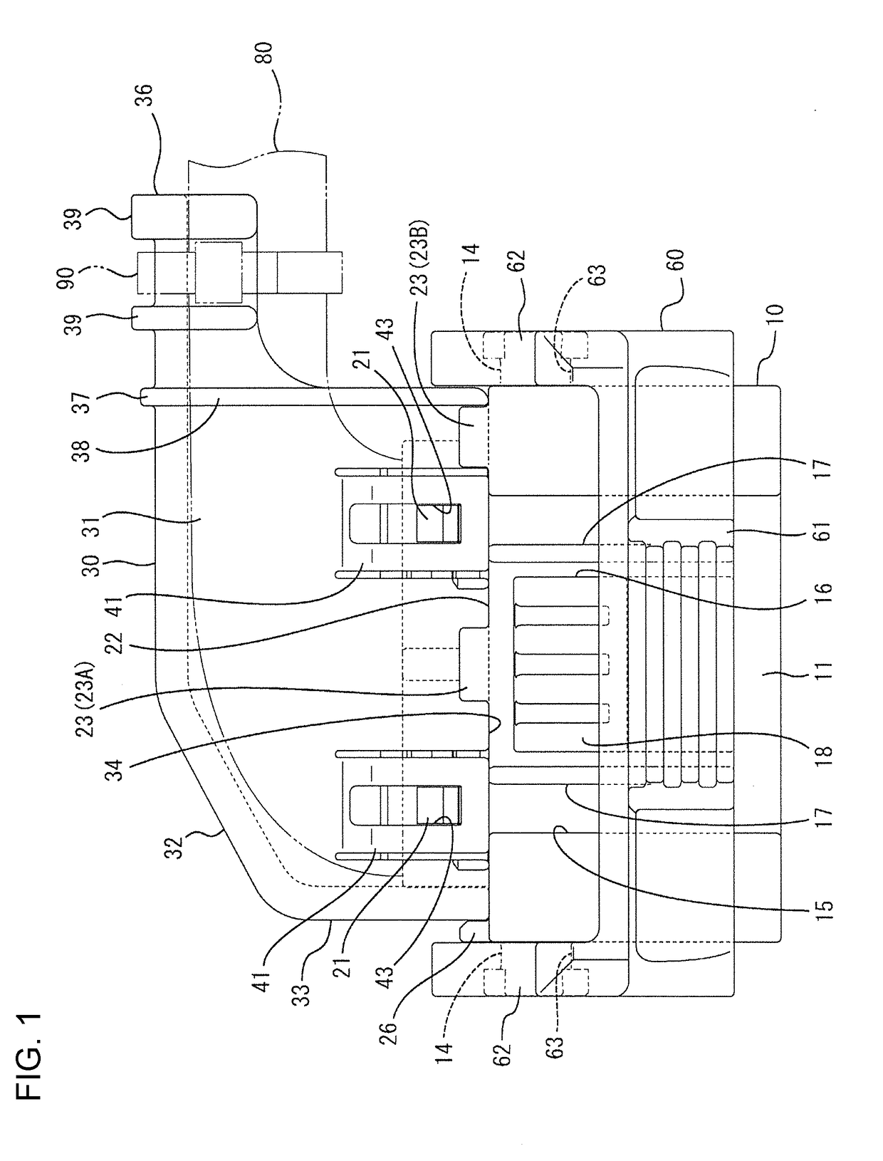
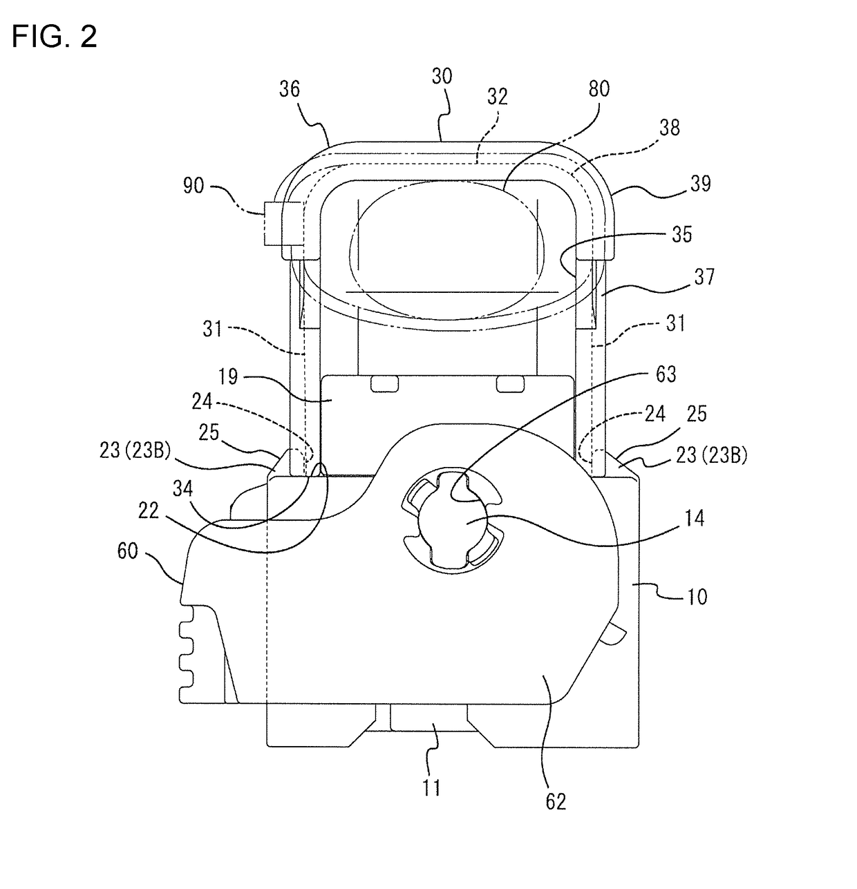
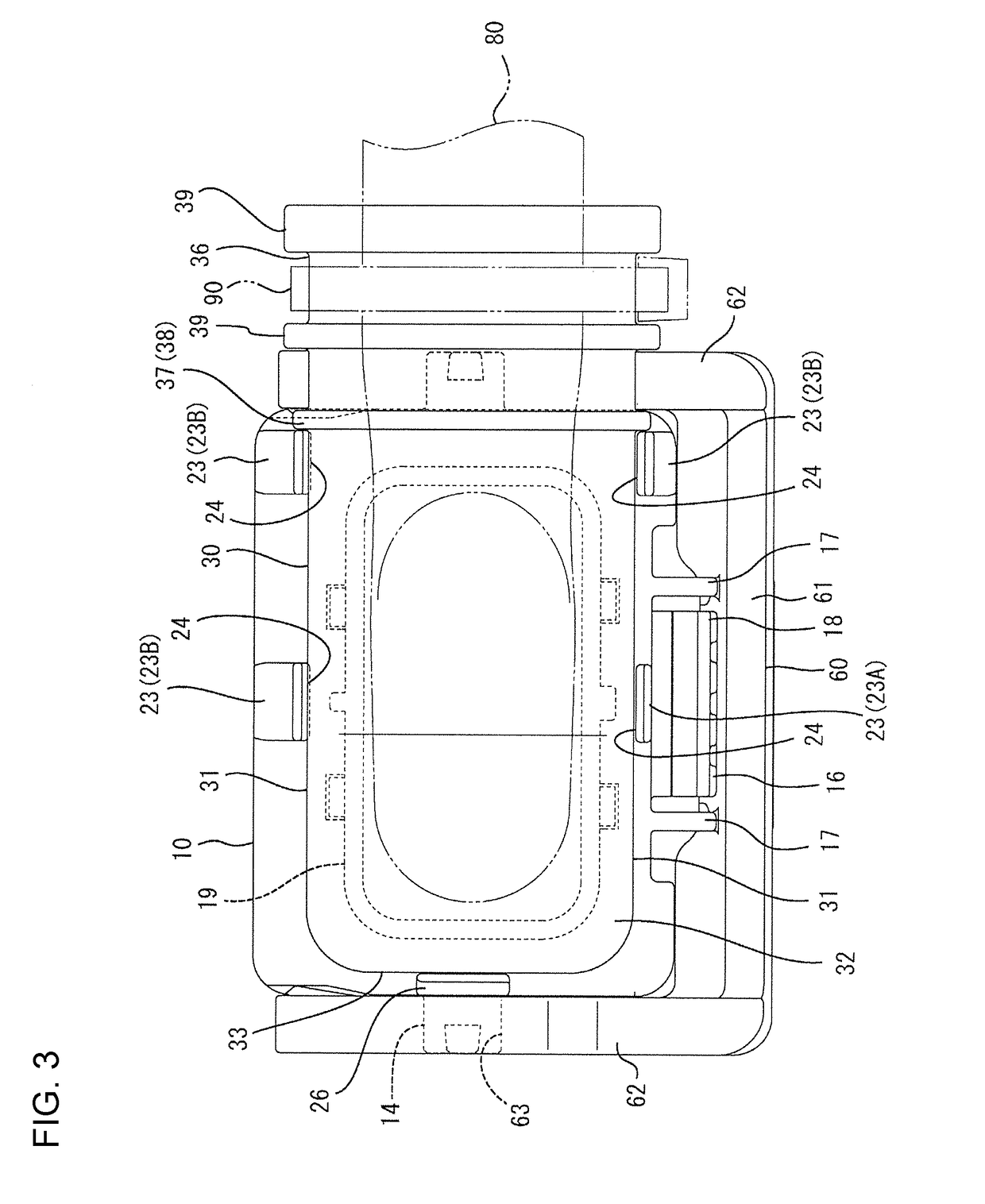
[0016]A connector of this embodiment includes a housing 10, a cover 30 to be assembled with the housing 10 and a lever 60 to be mounted rotatably on the housing 10. In the following description, a left side of each figure excluding FIG. 2 is referred to as a front concerning a front-rear direction and a vertical direction is based on a vertical direction of each figure excluding FIGS. 3 and 4.

[0017]The housing 10 is made of synthetic resin and includes, as shown in FIG. 4, a housing body 12 having cavities 11. An unillustrated terminal fitting is inserted into each cavity 11. The terminal fitting is connected to an end part of a wire 80. Each wire 80 extends up from a wire extending surface 13 serving as the upper surface of the housing body 12. Support shafts 14 project on both front and rear surfaces of the housing body 12. Each support shaft 14 has a substantially cylindrical shape and constitutes a pivot point of the lever 60. The lever 60 is made of synthetic resin, composed of...


PUM


Abstract

It is aimed to prevent the separation of a cover (30) from a housing (10). The housing (10) includes lock receiving portions (21) on an outer side of a wire extending surface (13). The cover (30) is in the form of a cap for covering wires (80) extending from the wire extending surface (13) and includes a wire pull-out opening (35) configured such that the wires (80) are pulled out therethrough, an opening end (34) configured to come into contact with the housing (10) along a front-rear direction, and lock portions (41) configured to restrict separation from the housing (10) by locking the lock receiving portions (21). The cover (30) includes a rib (37) serving as a forward movement restricting portion. The housing (10) includes opening restricting portions (23) arranged to contactably face a front end of the rib (37) and face an outer surface of the cover (30).

Description

BACKGROUNDField of the Invention[0001]The present invention relates to a connector.Related Art[0002]Japanese Unexamined Patent Publication No. H05-290924 discloses a connector that includes a connector housing from which a wire is pulled out, and a cap-like cover to be mounted on the connector housing. The cover covers the wire and includes a wire pull-out opening for pulling the wire to the outside. The connector housing includes a locking projection on an outer peripheral side, and the cover includes a box-shaped locking frame projecting toward the connector housing. The locking frame locks the locking projection to hold the cover on the connector housing.[0003]In the above case, an excessive stress is generated in the cover when the pulled-out wire is swung a large amount and both side walls of the cover may expand. This may cause the locking frame to disengage from the locking projection and the cover may separate from the connector housing.[0004]The present invention was comple...

Claims


Application Information

Patent Timeline
IPC IPC(8): H01R13/506H01R13/56
CPCH01R13/506H01R13/56
Inventor OGASHIRA, DAISUKE
Owner SUMITOMO WIRING SYST LTD
Why Eureka
Try Eureka