Inflatable sleeve with controlled expansion

Active Publication Date: 2019-10-15
CALYF
View PDF18 Cites 0 Cited by
  • Summary
  • Abstract
  • Description
  • Claims
  • Application Information

AI Technical Summary

Benefits of technology

[0050]Such an elongation rate makes it possible to obtain a hemispherical profile at the first end of the inflatable sleeve.
[0051]According to one alternative embodiment, the tubular sheath is rigidly fixed to the mandrel along a plurality of circumferences, distributed longitudinally between the first and second longitudinal ends. The sleeve thus includes, in addition to rings making it possible to fix the tubular sheath and the casing to the mandrel, a plurality of intermediate rings. The intermediate rings are for example regularly longitudinally spac

Problems solved by technology

However, a tubular sheath of this type cannot be used in the case where the desired profile at the longitudinal ends of the sheath, in the expanded state, has a hemispherical sha

Method used


Image

  • Inflatable sleeve with controlled expansion
  • Inflatable sleeve with controlled expansion
  • Inflatable sleeve with controlled expansion

Examples


Example

[0088]In a first example embodiment, the sheath is a woven sheath as shown in FIG. 5.

[0089]The sheath then includes a plurality of inextensible longitudinal yarns 31 and at least one extensible circumferential yarn 33.

[0090]These yarns are for example each made from natural fibers such as cotton, linen or hemp, or glass fibers, carbon fibers, or organic fibers such as aramid, para-aramid, polyester, polypropylene, polyamide, etc.

[0091]These yarns form folds when the tubular sheath is in its rest state. When the sheath is subjected to longitudinal traction or traction in the direction of a radial expansion, the yarns become stretched and the folds are undone.

[0092]The sheath also includes longitudinal elastic yarns 35 and at least one circumferential elastic yarn 37. The elastic yarns 35 and 37 become elongated at the same time as the inextensible yarns 31 and 33. They serve, when the elastic yarns 31 and 33 are unfolded, to return these yarns toward their folded configuration.

[0093]...

Example

[0100]In a second embodiment, the sheath is woven with yarns called structured yarns. These yarns are made from an inelastic material, and have a plurality of folds when at rest. When they are subject to traction, the folds are undone and the yarns become elongated. When the traction is interrupted, the yarns return to a folded shape on their own. It is therefore not necessary for the sheath to include elastic yarns in addition to structured yarns. The structured yarns can have elongation rates of up to 2.5.

Example

[0101]In a third embodiment, the sheath is woven with longitudinal yarns and at least one circumferential yarn that are each of the type described in the international patent application filed under number PCT / FR 2013 / 051381.

[0102]In an alternative embodiment that is not shown, the sheath is divided into two superimposed plies. A first ply incorporates the circumferential yarns with elastic, but not very strong longitudinal yarns, and the second ply incorporates the longitudinal yarns with elastic, but not very strong peripheral yarns. This makes it possible to eliminate the risks of wear of the peripheral yarns and the longitudinal yarns at their point of intersection.

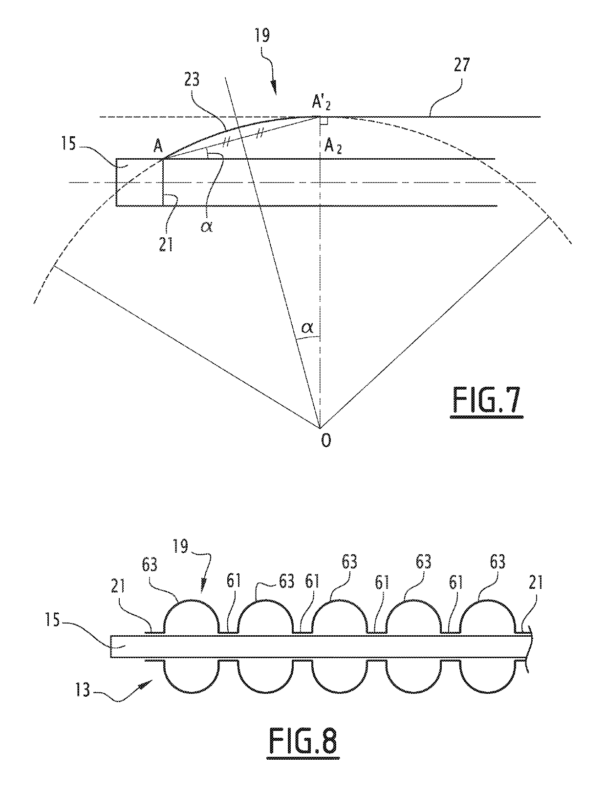
[0103]One alternative embodiment of the invention will now be outlined in reference to FIG. 8. Only the differences between the sleeve of FIG. 8 and that of FIGS. 1 to 4 will be outlined below. Identical elements or elements performing the same functions will be designated using the same references.

[0104]The sleeve of...


PUM


Abstract

The inflatable sleeve (13) comprises:
    • a mandrel (15) extending in a longitudinal direction;
    • an inflatable casing (17) placed around the mandrel (15);
    • a tubular sheath (19) slid around the casing (17), the tubular sheath (19) having a central segment (27) and first and second longitudinal ends (23, 25) situated on either side of the central segment (27), the first and/or second ends (23, 25) of the tubular sheath (19) being fixed to the mandrel (15), the tubular sheath (19) being extensible from a rest state to an expanded state.
The tubular sheath (19) has a predetermined circumferential elongation capacity from the rest state of the tubular sheath (19); and
    • the first and/or second ends (23, 25) of the tubular sheath (19) have a longitudinal elongation capacity from the rest state of the tubular sheath (19) comprised between 1.05 and 2.5, chosen to limit the diametric expansion of the first and/or second ends (23, 25) of the tubular sheath and give the first and/or second ends their shape (23, 25).

Description

CROSS-REFERENCE TO RELATED APPLICATIONS[0001]This application is the U.S. National Phase under 35. U.S.C. § 371 of International Application PCT / EP2014 / 067767, filed Aug. 20, 2014, which claims priority to French Patent Application No. 13 58077, filed Aug. 20, 2013. The disclosures of the above-described applications are hereby incorporated by reference in their entirety.FIELD OF THE INVENTION[0002]The invention generally relates to tubular sheaths, in particular inflatable sleeves used for diagraphy and the exploitation of underground boreholes.[0003]More specifically, the invention relates to an inflatable sleeve, the sleeve comprising:[0004]a mandrel extending in a longitudinal direction;[0005]an inflatable casing placed around the mandrel;[0006]a tubular sheath slid around the casing, the tubular sheath having a central segment and first and second longitudinal ends situated on either side of the central segment, the first and / or second ends of the tubular sheath being fixed to ...

Claims


Application Information

Patent Timeline
IPC IPC(8): E21B33/127
CPCE21B33/1277E21B33/127
Inventor COUR, FRANCIS
Owner CALYF
Why Eureka
Try Eureka