Insertion device for an insertion set and method of using the same
a technology of insertion device and insertion set, which is applied in the field of insertion device, can solve the problems of obstruction of medication flow to the patient, insufficient manual dexterity or skill to achieve proper needle placement, and difficulty in correct needle placement for proper administration of medication, etc., and achieves quick and easy separation of the injector, minimal patient discomfort, and minimal patient discomfort.
- Summary
- Abstract
- Description
- Claims
- Application Information
AI Technical Summary
Benefits of technology
Problems solved by technology
Method used
Image
Examples
first embodiment
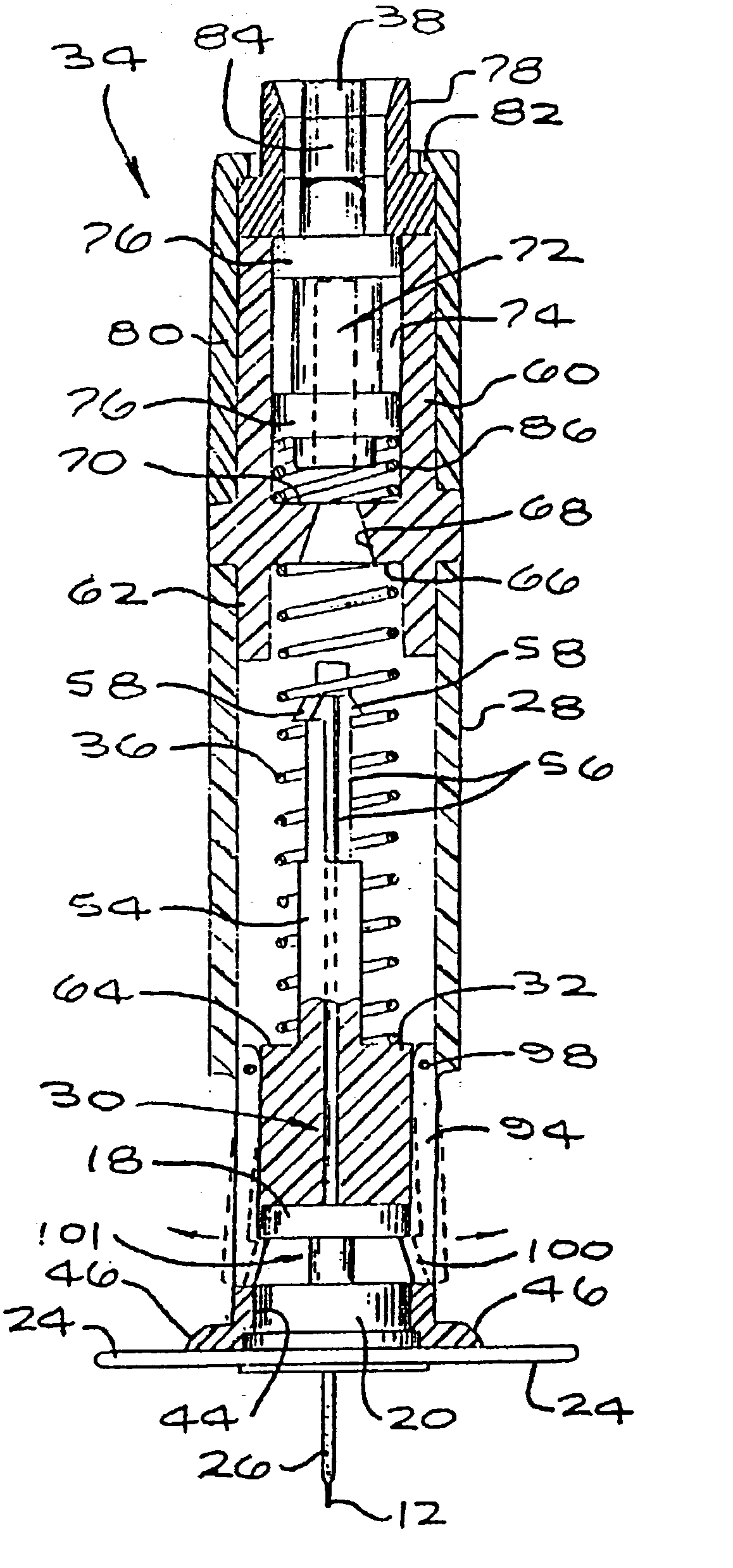
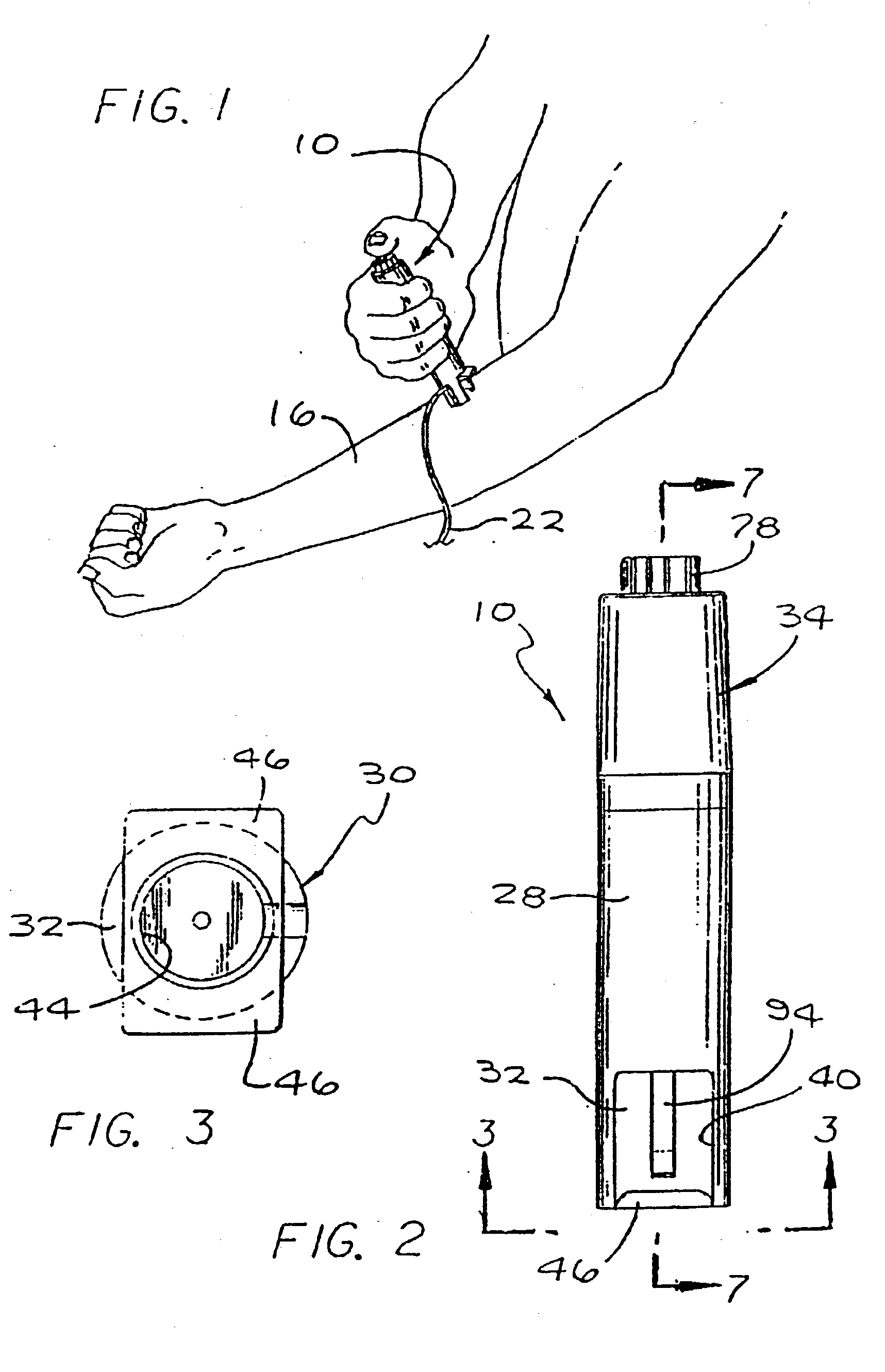
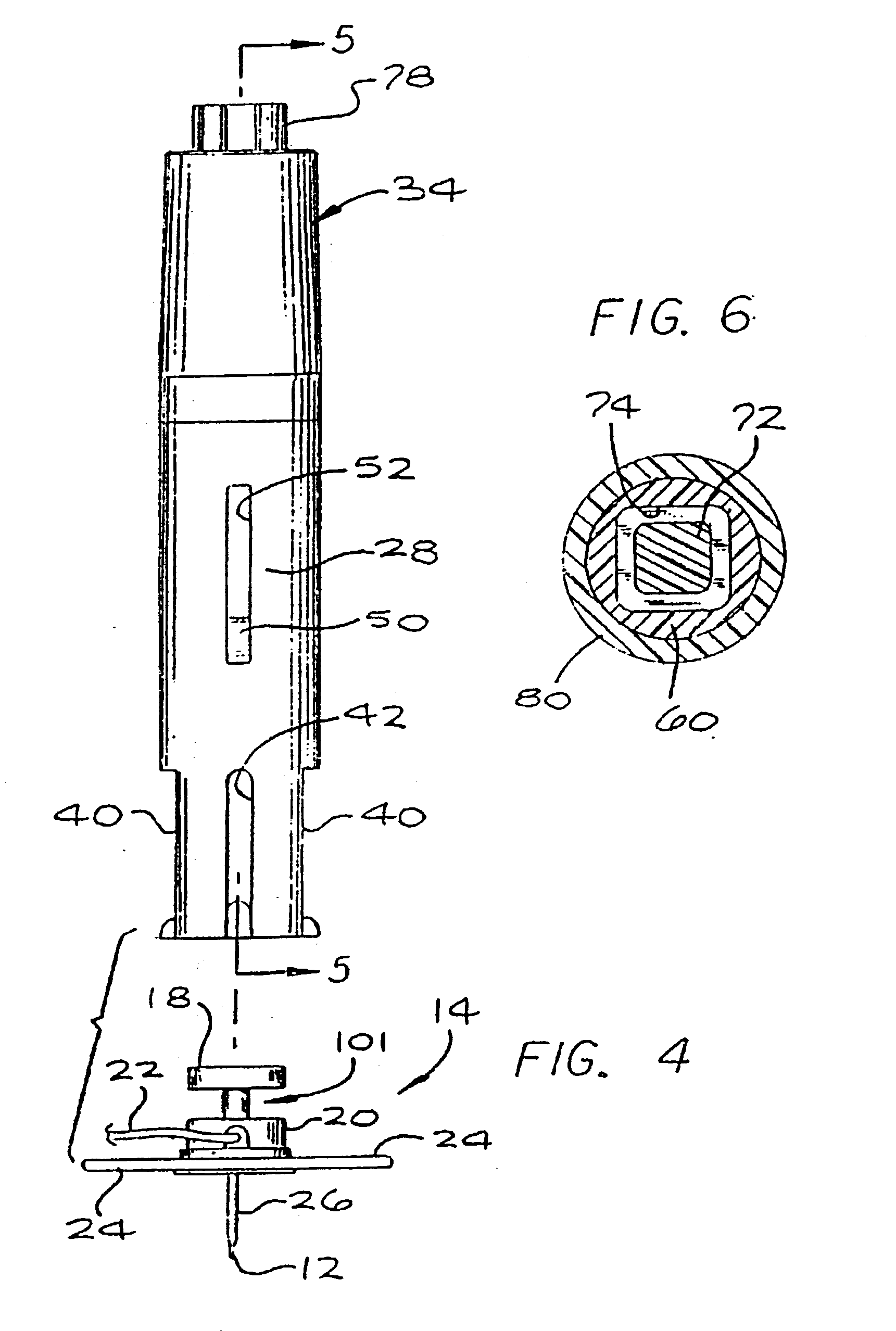
[0072] As shown in the exemplary drawings, an injector (or insertion device) in accordance with the present invention is referred to generally by the reference numeral 10 is provided for quick and easy transcutaneous placement of a medical needle, particularly such as an insertion needle 12 of the type provided with a subcutaneous insertion set 14 as depicted in FIGS. 4 and 7. The injector 10 includes a trigger-type actuator mechanism for transcutaneous placement of the insertion needle 12 with a controlled speed and force, and with the insertion needle 12 oriented at a desired angular position relative to the skin 16 (FIGS. 1 and 9) of the patient.
[0073] The automatic injector 10 of the present invention, as shown in the illustrative drawings, is particularly designed for placement of the insertion needle 12 of a subcutaneous insertion set 14, such as an insertion set of the general type shown and described in U.S. Pat. Nos. 4,755,173; 5,176,662; and 5,257,980, which are incorporat...
second embodiment
[0099]FIGS. 35-40g illustrate an insertion device 500 in accordance with the present invention. The insertion device 500 includes a barrel 502 (or device housing) having a surface seat 501 and an assembly port 503, a carrier body 504 (or plunger or the like) having an assembly rim 505 and a seating flange 506, a drive spring 507 (or driver), a release button 508, and dual spring triggers 510 and 512. As shown in FIG. 35, the barrel 502 performs as a housing to hold the carrier body 504. The carrier body 504 is connected to the barrel 502 by the carrier body being inserted through an opening in the surface seat 501 of the barrel 502, and then passing the assembly rim 505 of the carrier body 504 through the assembly port 503 of the barrel 502. The section of the carrier body 504 with the assembly rim 505 compresses slightly, as it passes through the assembly port 503, due to the presence of compression slots 509, and then essentially restores to its original shape to prevent the carri...
third embodiment
[0108]FIGS. 41-46 illustrate an insertion device 600 in accordance with a third embodiment that is similar to the insertion devices shown in FIGS. 1-34. The insertion device 600 includes a device housing end 601 and a carrier body 602 that has angled insertion contact surfaces 603 and 604. The angled insertion contact surfaces 603 and 604 enable the user to properly angle the insertion device 600 to insert an insertion set 700, or the like, at the proper insertion angle relative to the skin. An insertion set similar to the insertion set 700 is disclosed in U.S. patent application Ser. No. 08 / 871,831 (PCT Application Serial No. US98 / 10832) to Van Antwerp et al. entitled “Disposable Sensor Insertion Assembly” or an insertion set that can be inserted at an angle as disclosed in U.S. patent application Ser. No. 09 / 034,626 to Funderburk et al. entitled “Medication Infusion Set”, both or which are herein incorporated by reference. Preferred embodiments of the insertion device 600 have ang...
PUM
 Abstract
Description
Claims
Application Information
 - R&D
- Intellectual Property
- Life Sciences
- Materials
- Tech Scout
- Unparalleled Data Quality
- Higher Quality Content
- 60% Fewer Hallucinations
Browse by: Latest US Patents, China's latest patents, Technical Efficacy Thesaurus, Application Domain, Technology Topic, Popular Technical Reports.
© 2025 PatSnap. All rights reserved.Legal|Privacy policy|Modern Slavery Act Transparency Statement|Sitemap|About US| Contact US: help@patsnap.com


