Front or side controlled electrical shutoff apparatus

Active Publication Date: 2006-04-06
SOCOMEC
View PDF7 Cites 14 Cited by
  • Summary
  • Abstract
  • Description
  • Claims
  • Application Information

AI Technical Summary

Benefits of technology

[0006] The present invention proposes overcoming these disadvantages with a shutoff apparatus that is polyvalent and responsive to all

Problems solved by technology

However, these polyvalent shutoff apparatuses have complex, heavy transmission mechanisms with a large number of pieces and a

Method used


Image

  • Front or side controlled electrical shutoff apparatus
  • Front or side controlled electrical shutoff apparatus
  • Front or side controlled electrical shutoff apparatus

Examples


case 2 (

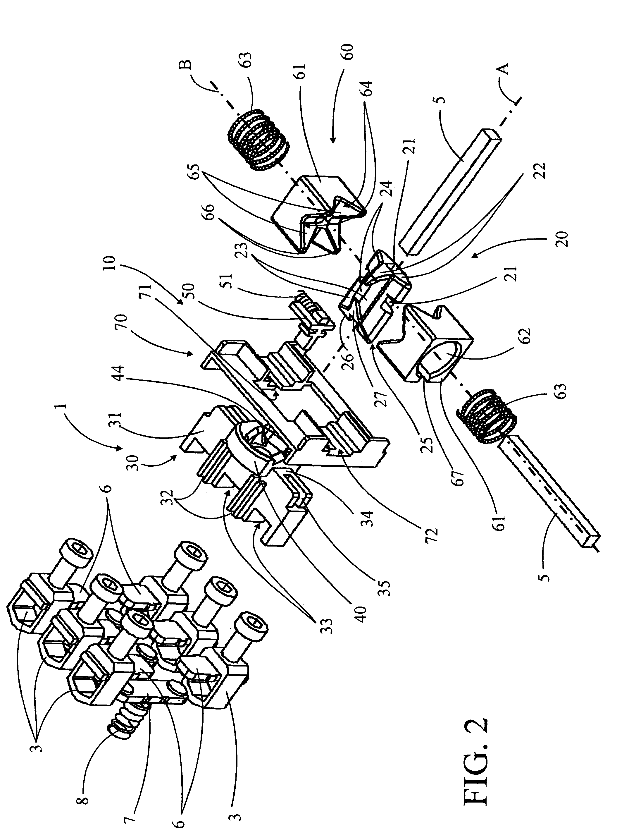
[0036] Case 2 (not shown) comprises an intermediate plate 70 disposed between transmission element 30 and the unit formed of the locking element 20 and pistons 61. This intermediate plate 70 specifically comprises a translational guide groove 71 for locking means 50 and translational guide openings 72 for pistons 61. It allows guided translational movement by these pieces and also distributes the restraining forces of the lock when it is in the locked position, thus sparing pistons 61.

[0037] The operation of shutoff apparatus 1 of the invention will now be described with reference to FIGS. 3 and 4, corresponding to front control mode, that is, using control axle A.

[0038]FIGS. 3A and 4A illustrate shutoff apparatus 1 in the released position. Rotating control elements 20 and transmission control elements 30 are in contact at their tips 26, 24, with linear finger 26 resting on tip 44 of multiple-cam block 40. Pistons 61 block rotating control element 20 in a stable position, with the...


PUM


Abstract

The present invention concerns a shutoff apparatus that can be controlled in either front or side mode, consisting of a minimum number of parts and resulting in a simple, economical, mechanically dependable, and compact unit. The shutoff apparatus (1) is characterized in that it comprises a rotating control element (20) in the shape a star with four branches (22), provided with a profiled extremity (25) and connected to the control rod (5) oriented toward one or the other of the two control axles (A, B) corresponding to front and lateral control modes, respectively. It comprises a transmission element (30) connected to movable contacts (7) and equipped with inclined ramps transforming rotational movement by the control element (20) on one or the other of the two control axles (A, B) into translational movement by the movable contacts (7) between the released and engaged positions, and conversely. It also comprises a sudden actuation device (60) with two pistons (61) comprising two orthogonal V-shaped grooves (64) acting on the rotation of the control element (20) from a position of equilibrium and from a locking element (50) blocking the transmission element (30) in the released position until the position of equilibrium is reached.

Description

FIELD OF THE INVENTION [0001] The present invention concerns a front or side controlled electrical shutoff apparatus for an electrical installation comprising at least one case equipped with at least one pair of connecting terminals for connection to at least one electrical conductor on said installation and connected to a pair of fixed contacts, said case comprising at least one movable contact and at least one control rod traversing said case, connected on the exterior to a manipulation device and on the interior to said movable contact by means of a transmission mechanism which displaces it between a released position, where the movable contact is separated from the fixed contacts and the electrical circuit is open, and an engaged position, where it touches the fixed contacts and the electrical circuit is closed. BACKGROUND OF THE INVENTION [0002] Such shutoff apparatuses are commonly called switches, fusible switches, reverse switches, commutators, reverse commutators, etc., and...

Claims


Application Information

Patent Timeline
IPC IPC(8): H01H9/26H01H33/02H01R13/62
CPCH01H11/0018H01H2011/0025H01H2300/048
Inventor DUMONT, ROGER
Owner SOCOMEC
Why Eureka
Try Eureka