
Image reading apparatus

Active Publication Date: 2006-04-06
KONICA MINOLTA BUSINESS TECH INC +1
View PDF8 Cites 19 Cited by
  • Summary
  • Abstract
  • Description
  • Claims
  • Application Information

AI Technical Summary

Benefits of technology

[0011] The present invention has been made in view of the above situation, and has as its object to provide an image reading apparatus in which the original conveyance stability while an original passes on a platen set at the original image reading position is improved to suppress blur or distortion of the read image.

Problems solved by technology

In the document feeder, even when the gap between the first glass platen and convey guide is regulated to be small, an impact which occurs when the scoop-up member scoops up the original from the first glass platen, the impact which occurs when the original enters delivery rollers, and the impact which occurs when the trailing edge of the original leaves convey rollers may adversely affect the read image to cause problems such as image blur.
Then, distortion occurs in the read image.
In order to prevent this, each time an original is to be conveyed, the biasing forces of the scoop-up member and convey guide must be adjusted, which is cumbersome.

Method used


Image

  • Image reading apparatus
  • Image reading apparatus
  • Image reading apparatus

Examples


Embodiment Construction

[0022] The preferred embodiment of an image reading apparatus according to the present invention will be described in detail with reference to the accompanying drawings.

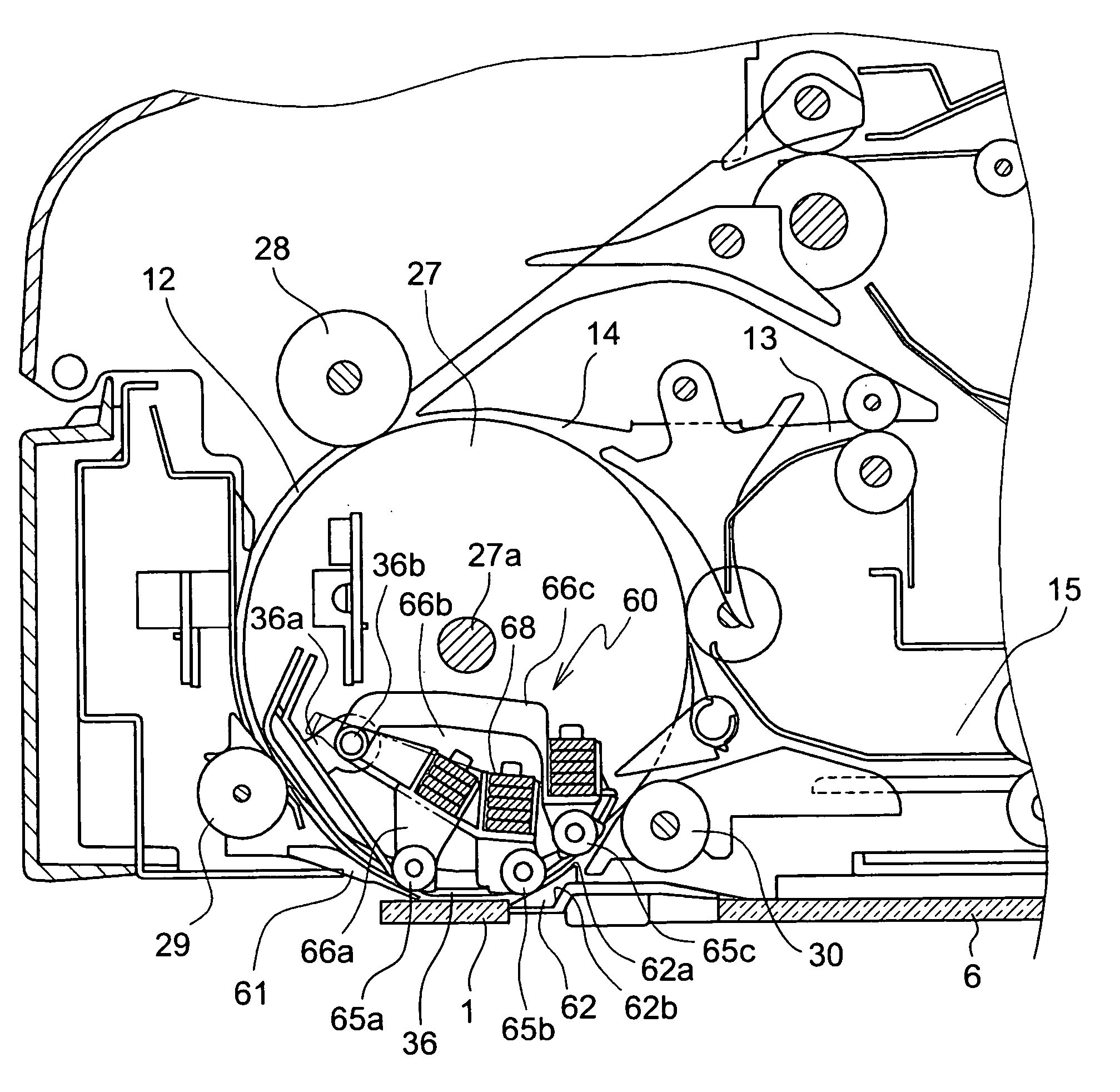
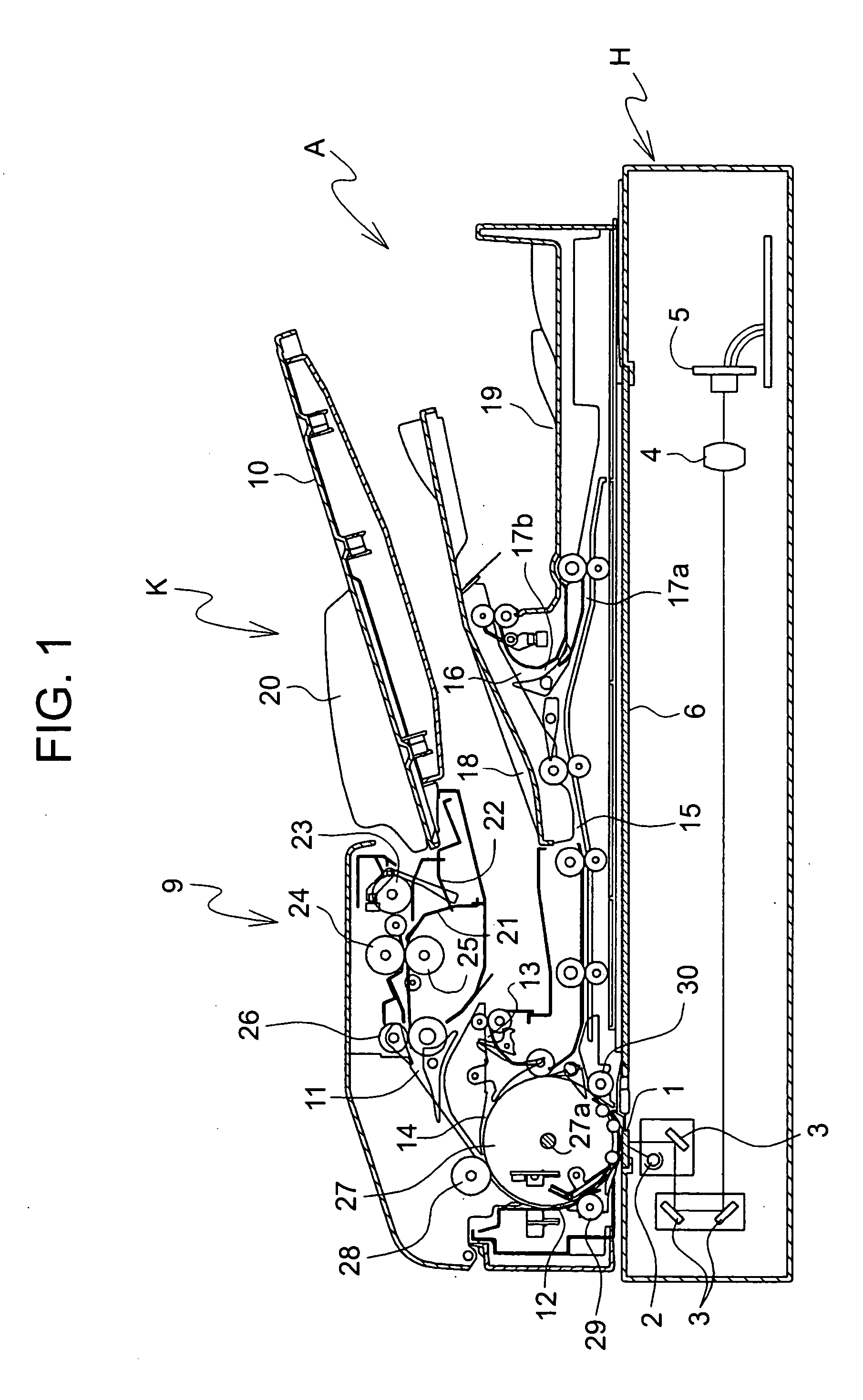
[0023]FIG. 1 shows the entire arrangement of an image reading apparatus according to the present embodiment, which includes an image reading apparatus main body H and a document feeder A mounted on it. An original picked up from a paper feeder K of the document feeder A passes the reading position of the image reading apparatus main body H and is delivered onto a delivery tray.

[0024] The document feeder A includes the paper feeder K having a paper feed tray 10 for placing a plurality of originals on it, and first and second delivery trays 18 and 19 which store the originals read by the image reading apparatus main body H. The first delivery tray 18 mainly stores large-sized originals, and the second delivery tray 19 stores small-sized originals.

[0025] The document feeder A has a plurality of sheet convey paths ext...


PUM


Abstract

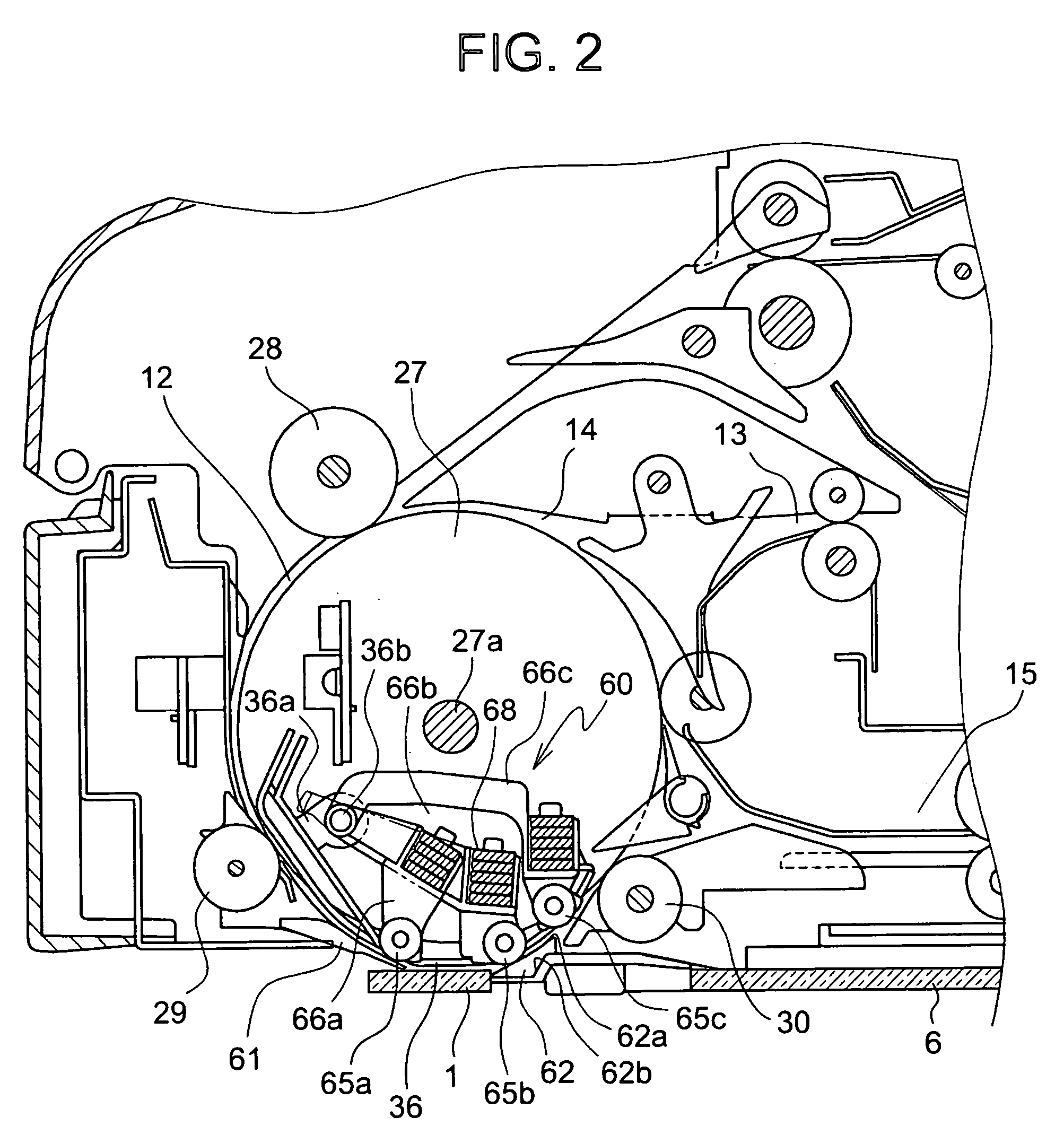
An image reading apparatus includes a platen which is set at an image reading position, a loading guide portion which is arranged upstream in a convey direction of an original to be adjacent to the platen and guides the original to an upper surface of the platen, a scoop-up guide portion which is arranged downstream in the convey direction of the original to be adjacent to the glass platen and guides a leading edge of the original, which has passed through the platen, by scooping up, a convey guide portion which is arranged to oppose the platen and scoop-up guide portion, to form a convey path between the convey guide portion and both of the platen and the scoop-up guide portion, a support portion which supports the convey guide portion to be slidable parallel to the platen, and a regulating portion which is arranged between the convey guide portion and the scoop-up guide portion to hold a constant gap between the convey guide portion and the scoop-up guide portion.

Description

[0001] This application is based on and claims the priority under 35 U.S.C. § 119 from the Japanese Patent Application No. 2004-241193 filed in Japan on Aug. 20, 2004, the entire content of which is incorporated herein by reference. BACKGROUND OF THE INVENTION [0002] 1. Field of the Invention [0003] The present invention relates to an image reading apparatus including a document (original) feeder for conveying an original (document) automatically and, more particularly, to an improvement in an original guide at a reading position. [0004] 2. Description of Related Art [0005] Conventionally, an image reading apparatus such as a digital copying machine, facsimile machine, or image scanner includes a document feeder which sends out a plurality of stacked originals one by one and conveys each original to a reading position automatically. The image reading apparatus directly reads the original fed to the reading position, i.e., by the so-called flow scanning scheme. [0006] An image readin...

Claims


Application Information

Patent Timeline
IPC IPC(8): B65H5/22
CPCH04N1/1215H04N1/123H04N1/1235H04N2201/0456
Inventor MIZUBATA, TSUYOSHIHATA, KIYOSHIOGAWA, MASAHIROYAMADA, HIROYUKIHIGUCHI, MASAKI
Owner KONICA MINOLTA BUSINESS TECH INC
Learn More