
Battery pack and its method of manufacture

a battery pack and battery technology, applied in the field of batteries, can solve the problems of high cost, difficult to manufacture, and difficulty in adjusting the temperature of the battery pack, and achieve the effect of reducing the cos

Inactive Publication Date: 2006-04-06
SAMSUNG SDI CO LTD
View PDF6 Cites 31 Cited by
  • Summary
  • Abstract
  • Description
  • Claims
  • Application Information

AI Technical Summary

Benefits of technology

[0013] Accordingly, the present invention has been made to solve the above-mentioned problems, and an object of the present invention is to provide a battery pack having no need to fill the gap between a bare cell and a protective circuit module so that its cost decreases and a PTC thermistor does not degrade its characteristics, and its method of manufacture.
[0014] Another object of the present invention is to provide a batter pack having a lead positioned on a safety vent formed on a bare cell to prevent resin from contacting or passing through the safety vent so that the safety vent can normally function when the bare cell swells, and its method of manufacture.
[0015] Still another object of the present invention is to provide a battery pack having no need to entirely mold a bare cell and a protective circuit module when forming a case to obviate a high temperature being transmitted to a PTC thermistor and degrading its characteristics, and its method of manufacture.
[0029] The resin preferably fills a gap between the long-sided and short-sided regions of the can and the case and extends to a level corresponding to 50-90% of an overall height of the case from the bottom side.
[0037] The battery pack and its method of manufacture according to the present invention are advantageous in that, since the bare cell and the protective circuit module are enclosed by an integral case to fix them and a resin is used to fill only a part exposed by the case, the gap between the bare cell and the protective circuit module does not need to be filled with a resin. This reduces cost and prevents the protective circuit module and the PTC thermistor from being damaged.
[0038] Since a lead is positioned on the surface of the safety vent formed on the bare cell, the safety vent does not fracture during resin filling. Particularly, a resin of high temperature and pressure does not contact or pass through the safety vent during resin filling process, so that the safety vent is not fractured by it. As a result, the safety vent functions normally in the case of swelling and minimizes the danger of explosion.

Problems solved by technology

However, such a battery pack has a problem in that molding must be performed using a resin to mechanically fix the protective circuit module and the bare cell.
Then, various electronic components on the protective circuit module are easily damaged and the lead and the PTC thermistor, which have previously been connected to each other, can detach from each other.
Since the resin has a temperature of about 150° C. when filling the gap between the bare cell and the protective circuit module, the PTC thermistor is very likely to be actuated and degrade its characteristics.
However, the PTC thermistor is then exposed to the danger of hitting other objects and being damaged by them during manufacturing processes.
This makes the manufacturing processes complicated and increases cost.
This further increases the manufacturing cost of the battery pack and, as the processes become more complicated, the defect ratio increases.
When the bare cell is enclosed by a resin to shape a case of a battery pack, however, the resin having a high temperature and pressure can pass through the safety vent and partially penetrate into the bare cell.
In this case, the safety vent may fail to function even when the internal pressure of the bare cell rises.
If the safety vent does not function properly, the bare cell is subjected to a very high pressure and eventually explodes or catches fire at a critical pressure.
This seriously degrades the reliability of the battery pack.

Method used


Image

  • Battery pack and its method of manufacture
  • Battery pack and its method of manufacture
  • Battery pack and its method of manufacture

Examples


Embodiment Construction

[0047] Hereinafter, exemplary embodiments of the present invention are described with reference to the accompanying drawings. In the following description and drawings, the same reference numerals are used to designate the same or similar components, and so a repetition of the description of the same or similar components has been omitted.

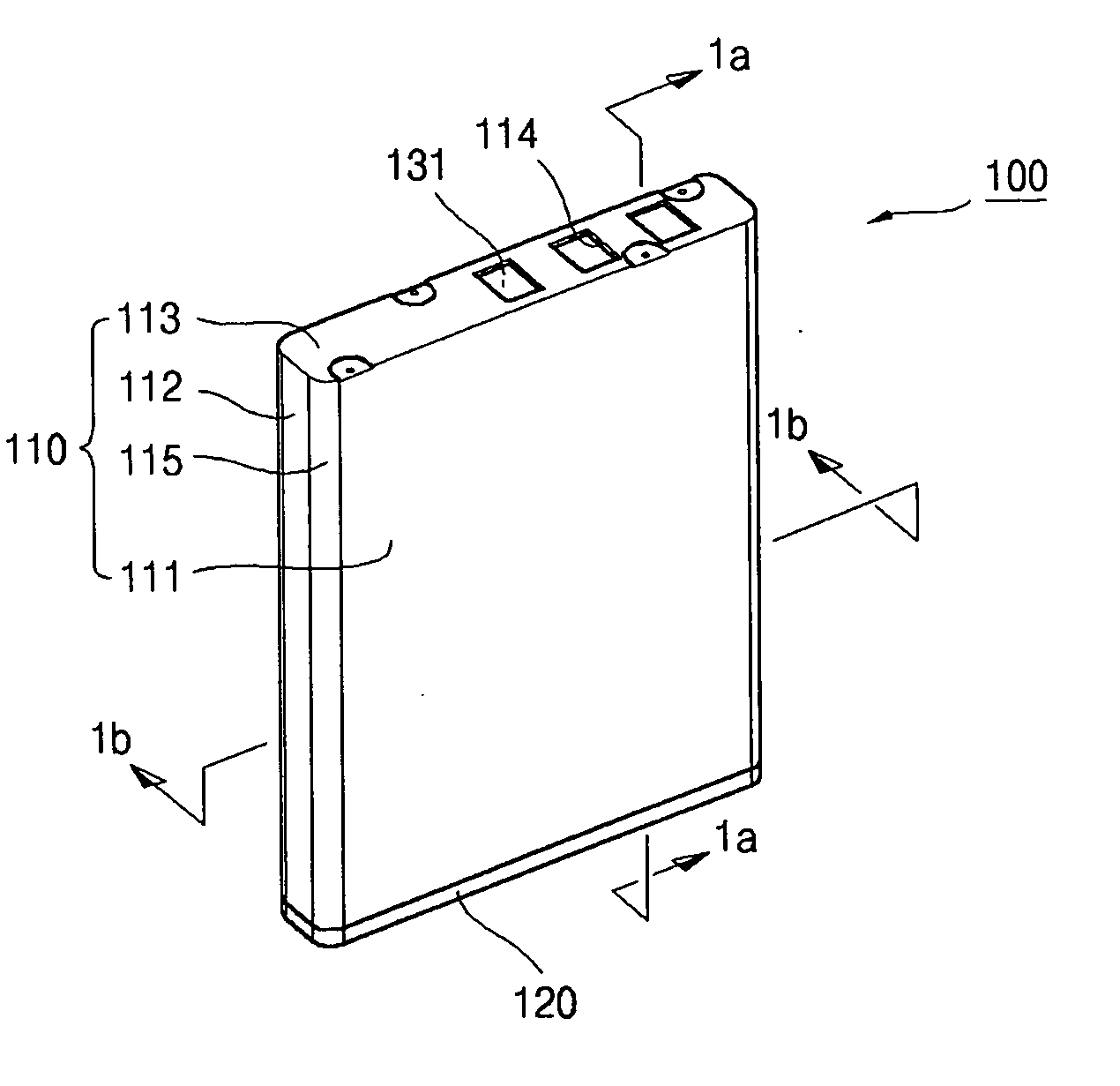
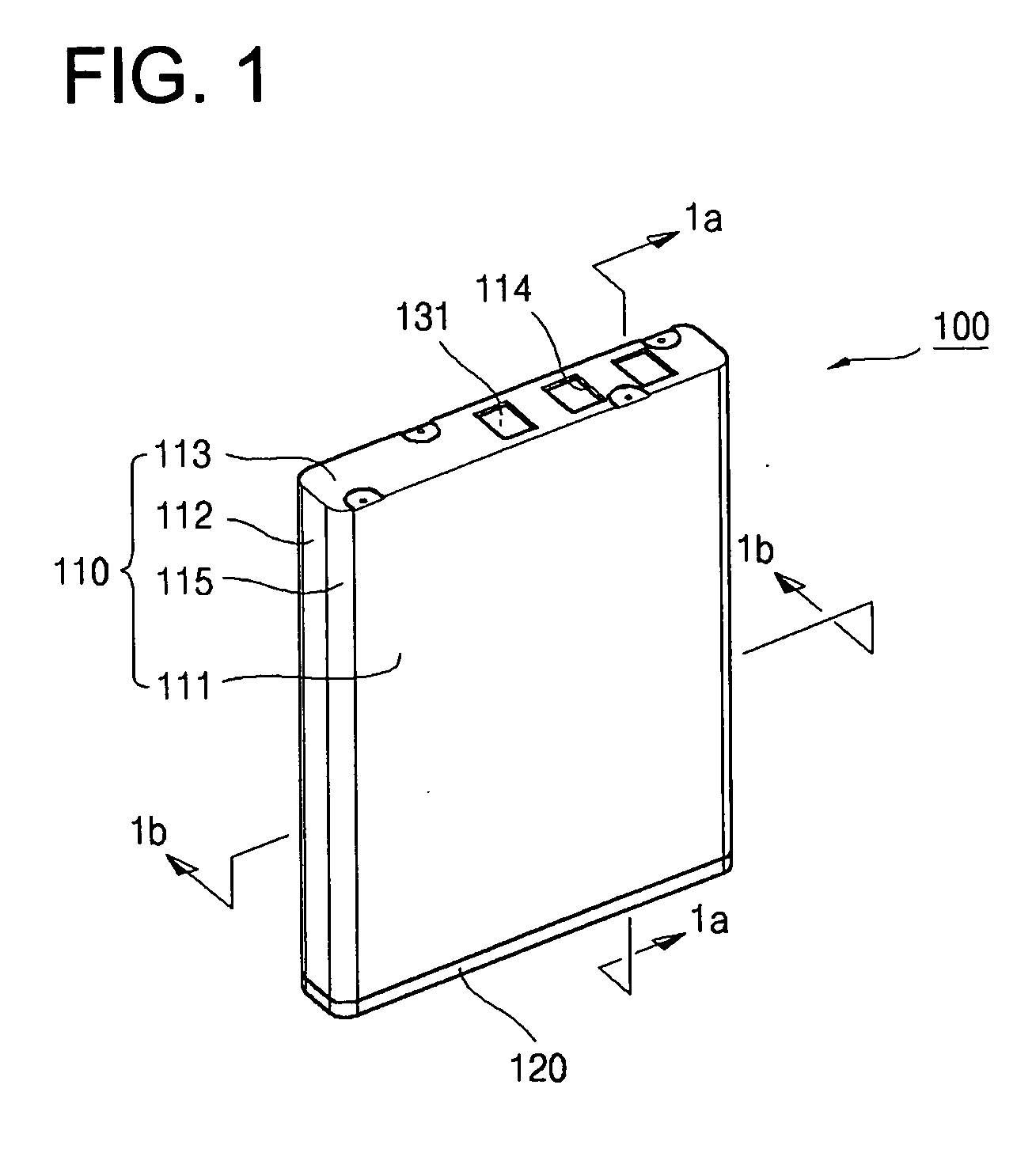
[0048]FIG. 1 is a perspective view of a battery pack according to an embodiment of the present invention.

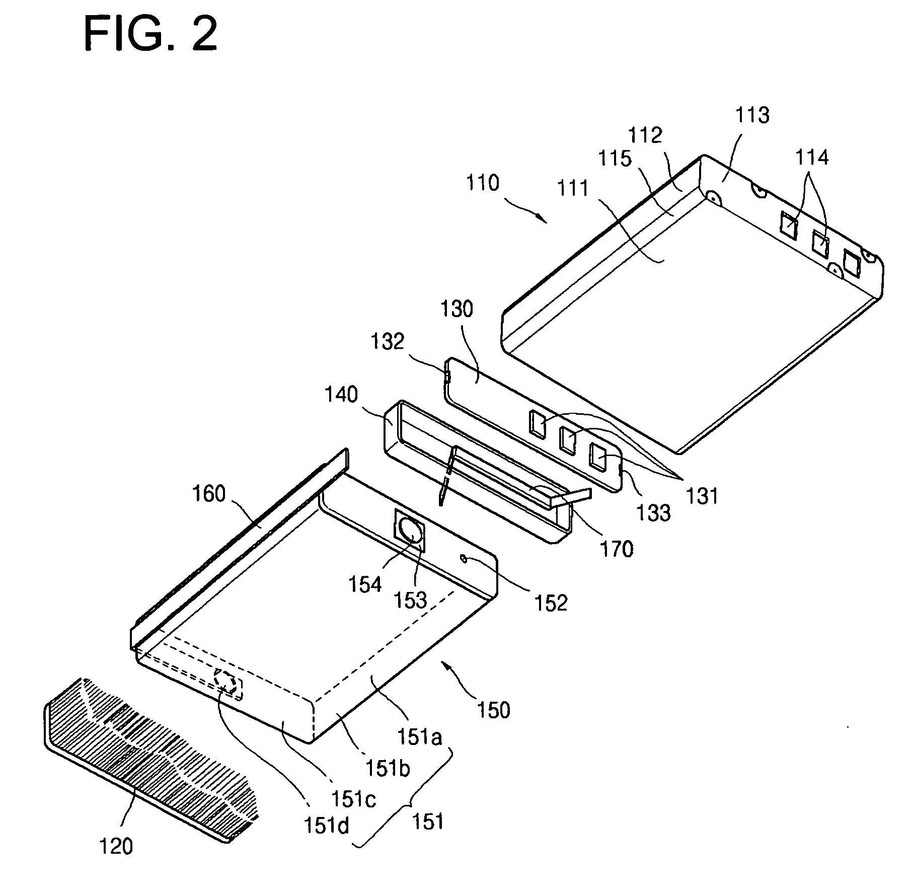
[0049] As shown in FIG. 1, the exterior of a battery pack 100 according to an embodiment of the present invention is enclosed by an approximately hexahedral case 110. The case 110 includes long-sided regions 111 spaced apart from each other and short-sided regions 112 positioned on the edges of the long-sided regions 111 while being spaced apart from each other. The area of the short-sided regions 112 is less than that of the long-sided regions 111. The case 110 can further include round portions 115 formed with a predetermined radius at the i...


PUM


Abstract

A battery pack having no need to fill a gap between a bare cell and a protective circuit module includes a safety vent adapted to properly function even after molding has been completed and a PTC thermistor having characteristics which do not degrade during manufacturing processes. A bare cell, which has a protective circuit module and a PTC thermistor mounted thereon, is enclosed by an integral case. An exposed area of the case is covered with a resin. A lead is positioned on a safety vent formed on the bare cell to prevent the safety vent from being fractured by a resin of a high temperature and pressure during a resin filling process. The resin does not reach the protective circuit module and the PTC thermistor so that its heat is not transmitted to them.

Description

CLAIM OF PRIORITY [0001] This application makes reference to, incorporates the same herein, and claims all benefits accruing under 35 U.S.C. §119 from an application for BATTERY PACK AND ITS METHOD OF MANUFACTURE earlier filled in the Korean Intellectual Property Office on 22 Sep. 2004 and there duly assigned Serial No. 2004-0076143. BACKGROUND OF THE INVENTION [0002] 1. Field of the Invention [0003] The present invention relates to a battery pack and its method of manufacture, and more particularly to a battery pack having no need to fill the gap between a bare cell and a protective circuit module and including a safety vent adapted to properly function even after packing has been completed and a PTC thermistor having characteristics which do not degrade during manufacturing processes, and its method of manufacture. [0004] 2. Description of the Related Art [0005] In general, a battery pack includes a chargeable / dischargeable bare cell, a protective circuit module electrically coupl...

Claims


Application Information

Patent Timeline
IPC IPC(8): H02J7/00H01M50/574
CPCH01M2/12H01M2/34H01M10/42H01M2200/106Y02E60/10H01M50/30H01M50/574H01M50/20H01M50/572
Inventor HEO, SANG-DOKIM, IN-HAN
Owner SAMSUNG SDI CO LTD
Learn More