Picture buffering method

a buffering method and picture technology, applied in the field of buffering media data, can solve the problems of packet loss in fixed ip networks in bursts, the decoding order cannot be reconstructed from the frame numbers, and the error propagation to the rest of the inter picture prediction chain, so as to improve the error resiliency and improve the compression efficiency

Active Publication Date: 2006-04-06
NOKIA TECHNOLOGLES OY
View PDF76 Cites 66 Cited by
  • Summary
  • Abstract
  • Description
  • Claims
  • Application Information

AI Technical Summary

Benefits of technology

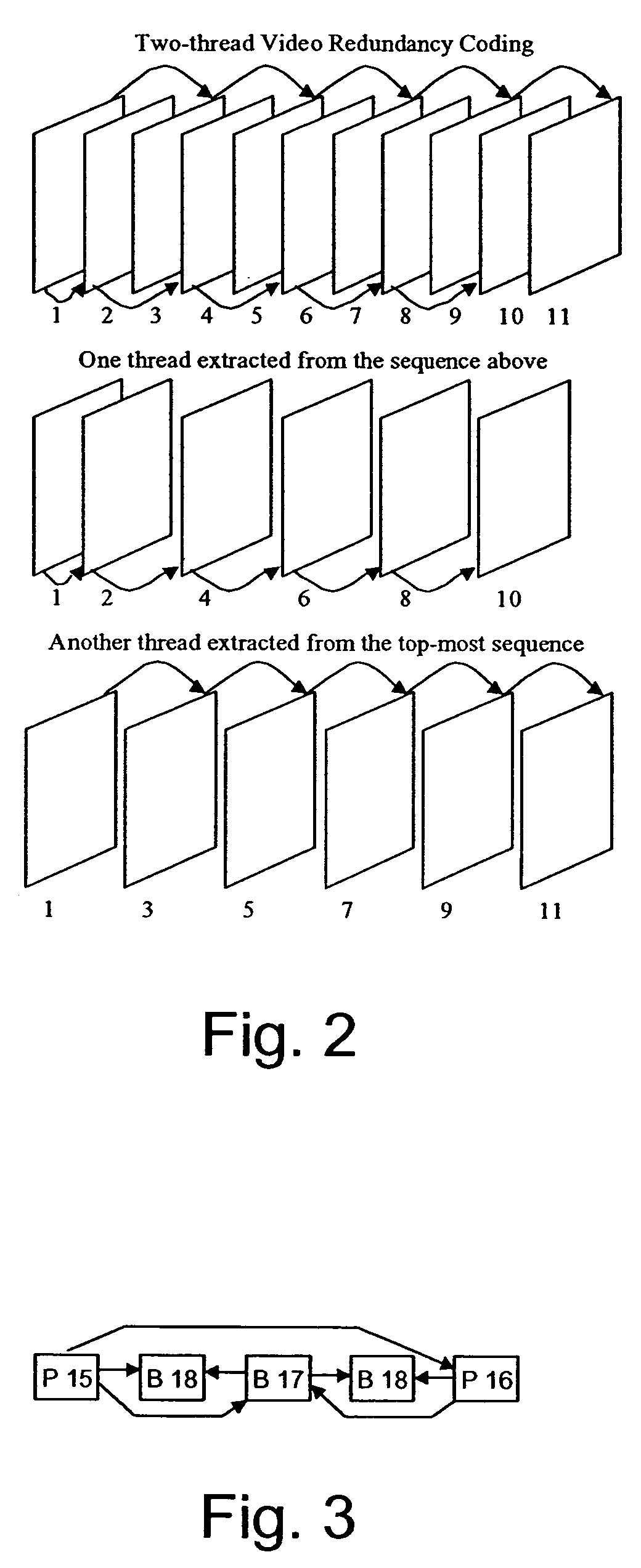
[0149]FIG. 3 presents an example of a prediction structure potentially improving compression efficiency,
[0150]F

Problems solved by technology

In conventional coding, a packet loss always causes error propagation to the rest of the inter picture prediction chain.
However, because the complementary reference field pairs (consecutive pictures coded as fields that are of different parity) share the same frame number, their decoding order cannot be reconstructed from the frame numbers.
Moreover, packets are typically carried on top of a best-effort network that cannot guarantee a constant transmission delay, but rather the delay may vary from packet to packet.
Second, it is commonly known that packet losses in fixed IP networks occur in bursts.
Instead, the systems prefer unreliable tra

Method used


Image

  • Picture buffering method
  • Picture buffering method
  • Picture buffering method

Examples


Embodiment Construction

[0157] An example of a scheme where the invention can be applied follows. The sequence is spliced into pieces of a number of transmission units. The transmission units are transmitted in the following transmission order, where the numbers indicate the decoding order numbers of the transmission units: [0158] 0, 8, 12, 2, 24, 14, 31, . . .

[0159] If the decoder buffer receives all the above mentioned transmission units, the calculated maximum (absolute) difference between decoding order numbers of transmission units in the decoding buffer are as follows, if no transmission units are outputted from the buffer:

[0160] after the second transmission unit, the difference would be 8 (the absolute difference between the first and the second decoding order number);

[0161] after the third transmission unit, the difference would be 12 (the absolute difference between the first and the third decoding order number);

[0162] after the fourth transmission unit, the difference would be 12 (the absolu...


PUM


Abstract

A method for buffering media data in a buffer where the media data is included in data transmission units which have been ordered in a transmission order which is at least partly different from a decoding order of the media data in the data transmission units. The decoding order is indicated with a quantitative indicator for at least part of the transmission units. In the method a parameter is defined for a relation of the quantitative indicators of transmission units. The relation of transmission units in the buffer is checked against the parameter. The result of the checking is indicative of at least one transmission unit in the buffer preceding, in decoding order, any transmission unit in a sequence of transmission units not having been buffered in the buffer before the checking.

Description

FIELD OF THE INVENTION [0001] The present invention relates to a method for buffering media data. The invention also relates to a system, transmitting device, receiving device, an encoder, a decoder, an electronic device, a computer product, and a signal. BACKGROUND OF THE INVENTION [0002] Published video coding standards include ITU-T H.261, ITU-T H.263, ISO / IEC MPEG-1, ISO / IEC MPEG-2, and ISO / IEC MPEG-4 Part 2. These standards are herein referred to as conventional video coding standards. Video Communication Systems [0003] Video communication systems can be divided into conversational and non-conversational systems. Conversational systems include video conferencing and video telephony. Examples of such systems include ITU-T Recommendations H.320, H.323, and H.324 that specify a video conferencing / telephony system operating in ISDN, IP, and PSTN networks respectively. Conversational systems are characterized by the intent to minimize the end-to-end delay (from audio-video capture ...

Claims


Application Information

Patent Timeline
IPC IPC(8): H04L12/56
CPCH04N21/23406H04N21/44004H04N19/172H04N19/46H04N19/423H04N19/44H04N19/89H04N19/31H04N19/114
Inventor HANNUKSELA, MISKA
Owner NOKIA TECHNOLOGLES OY
Why Eureka
Try Eureka