Image forming apparatus

Inactive Publication Date: 2006-04-06
SEIKO EPSON CORP
View PDF0 Cites 22 Cited by
  • Summary
  • Abstract
  • Description
  • Claims
  • Application Information

AI Technical Summary

Benefits of technology

[0014] Accordingly, it is advantages of the present invention to provide an inexpensive image-forming apparatus which diminishes noise stemming from a rotary development device and can perform silent image-forming operation by diverting use of a member located in the vicinity of the rotary development device without arranging a custom-designed member for lessening the noise of the rotary development device, and which can lessen the influence of heat to toner in a rotary development device by diverting the use of members arranged around the rotary development device and without placement of a member specifically designed to block the heat imparted to the rotary development device from the environment, thereby enabling formation of a highly-reliable, high-quality image, and which facilities performance of maintenance on an exhaust duct by making the exhaust duct removable without involvement of any special work and which can provide a high-quality image in a convenient manner.

Problems solved by technology

For this reason, difficulty is encountered in transferring all particles of the toner on the outer peripheral surface of the development roller to the image carrier or recovering all particles of the toner into the development cartridge.
Therefore, noise stemming from driving of the rotary development device, particularly, leakage of noise from a side surface close to a position where the rotary development device is situated, raises a problem.
For instance, when an ambient temperature becomes high, a problem may arise in the quality of the toner.
Since an internal storage space of the equipment also becomes smaller, difficulty is encountered in avoiding a layout where a rotary development device housing the development cartridges becomes close to heat-producing elements.
Even when the sucked toner has been accumulated in the exhaust path, the toner cannot be cleaned.
Therefore, on some occasions, when the image-forming apparatus has been subjected to shock during, e.g., movement, there may be a risk of the accumulated toner contaminating the inside of the apparatus.
Consequently, when the rotary development device is driven, the amount of noise leaking out of the side section is large.

Method used


Image

  • Image forming apparatus
  • Image forming apparatus
  • Image forming apparatus

Examples


first embodiment

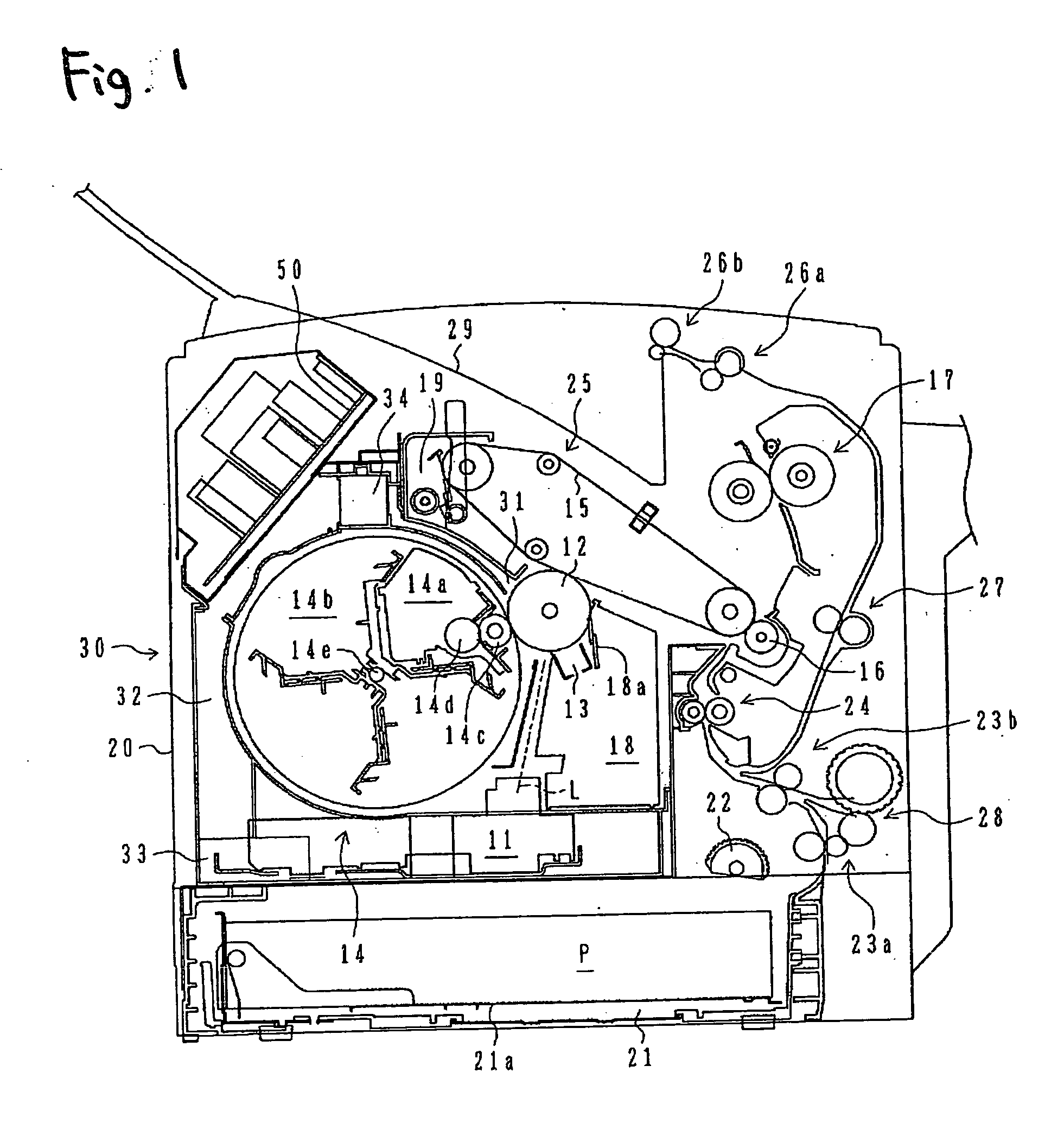
[0067] Best modes for implementing the present invention will be described hereinbelow by reference to the drawings. FIGS. 1 to 6 are drawings showing an image-forming apparatus according to the present invention.

[0068] In FIG. 1, an image-forming apparatus is a printer which is utilized while being connected to an external device, such as a personal computer, which prepares and outputs images, such as characters. This image-forming apparatus comprises an image recorder which receives image data pertaining to a target image to be formed as an image, such as characters, and records and forms the image on one or both surfaces of recording paper P (a recording medium) by means of electrophotography; and a paper transporter which transports a plurality of sheets of loaded recording paper P to the image recorder and also transports, to the outside of the image-forming apparatus in a stacking manner, the recording paper P on which an image has been recorded and formed.

[0069] Briefly, the...

second embodiment

[0090] Next, FIG. 7 is a view showing the image-forming apparatus of the present invention. Since the embodiment is substantially identical in configuration with the previously-described embodiment, corresponding constituent elements are assigned the same reference numerals, and only characteristic portions of the constituent elements are described (the same also applies to any counterparts in other embodiments which will be described below).

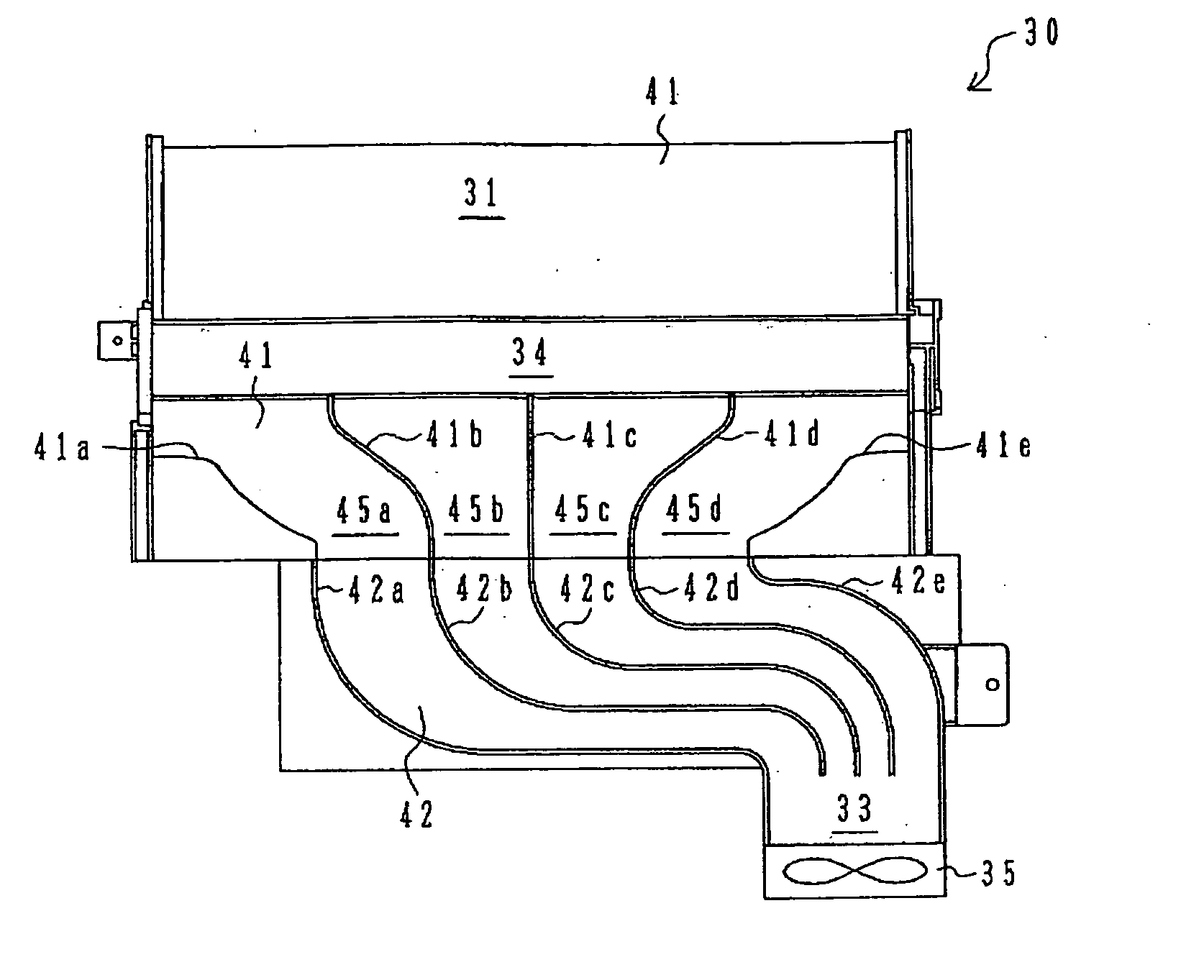
[0091] In FIG. 7, the image-forming apparatus also has an exhaust duct 60 in addition to having the exhaust duct 30.

[0092] In contrast with the exhaust duct 30 having the inlet 31 which is disposed in an upper position in the vicinity of the development position of the rotary development device 14, the exhaust duct 60 has an inlet 61 provided at a lower position in the vicinity of the development position (a position upstream of the development roller 14c and the photosensitive drum 12 with respect to their rotational directions). As in the cas...

third embodiment

[0099]FIG. 8 is a view showing the image-forming apparatus according to the present invention.

[0100] In FIG. 8, as in the case of the above-described embodiment, the image-forming apparatus is formed as having the image recorder and the paper transporter. In this image-forming apparatus, the recording paper P is caused to pass through the transport path provided on substantially the right side surface of the image-forming apparatus in the above-described embodiments, whereby the recording paper P is transported between the intermediate transfer belt 15, the transfer roller 16, and the pair of fusing rollers 17 in a nipped manner. Thus, an image is formed on one surface of the recording paper. The recording paper P withdrawn from the paper cassette 21 is inverted and transported horizontally. The recording paper P is transported between an intermediate transfer belt 75, a transfer roller 76, and a pair of fusing rollers 77 in a nipped manner, thereby forming an image.

[0101] Briefly ...


PUM


Abstract

An electrostatic latent image is formed on an image carrier. A plurality of development cartridges include toner and are adapted to face the image carrier at a development position, respectively. The development cartridges cause the toner to adhere onto the image carrier to develop the electrostatic latent image as a toner image. A development device is configured to be rotatable around an rotational axis thereof. The development device houses the plurality of development cartridges around the rotational axis. A duct includes an inlet port through which air in the vicinity of the development position is sucked and an outlet port from which the sucked air is exhausted to the outside of the image forming apparatus. The duct covers an outer peripheral surface of the development device.

Description

BACKGROUND OF THE INVENTION [0001] The present invention relates to an image-forming apparatus, and more particularly, to an image-forming apparatus provided with an exhaust duct. [0002] In an image-forming apparatus employing an electrophotographic recording system, an electrostatic latent image is formed through exposure on the surface of an image carrier formed from a photosensitive element. In this image-forming apparatus, the toner image formed on the surface of the image carrier, the toner image being transferred after the electrostatic latent image has been developed by use of toner, is transferred to a recording medium, such as recording paper, thereby forming an image. The electrostatic latent image can be subjected to toner development, by rotating a development roller opposing the surface of the image carrier and transferring the electrostatic latent image to an outer peripheral surface of the development roller in an adhering manner. [0003] This image-forming apparatus a...

Claims


Application Information

Patent Timeline
IPC IPC(8): G03G21/20
CPCG03G2215/0177G03G2221/1645G03G21/206
Inventor MIYAMOTO, SATORUSEGAWA, YUICHI
Owner SEIKO EPSON CORP
Why Eureka
Try Eureka