Oscillator circuit resistant to noise and jitter

Active Publication Date: 2021-06-01
SAMSUNG ELECTRO MECHANICS CO LTD
View PDF7 Cites 0 Cited by
  • Summary
  • Abstract
  • Description
  • Claims
  • Application Information

AI Technical Summary

Benefits of technology

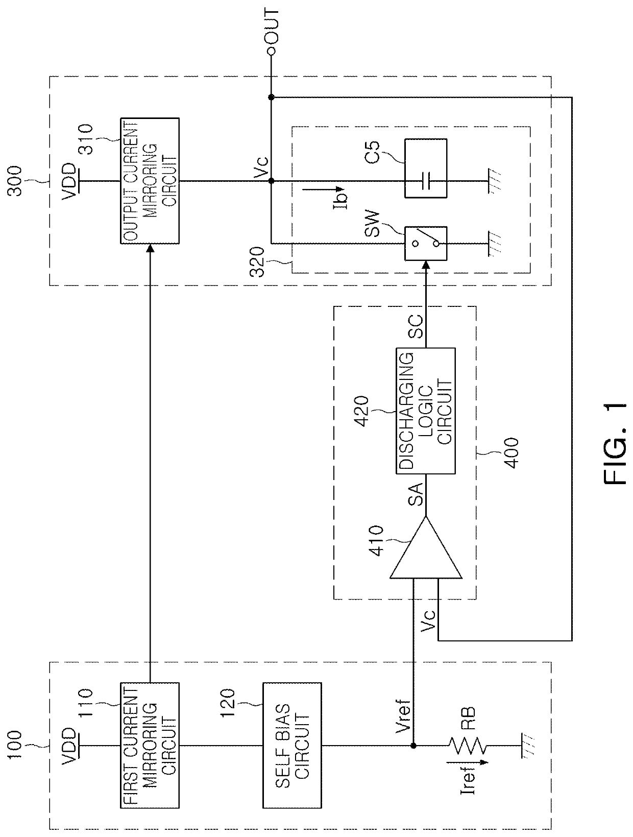
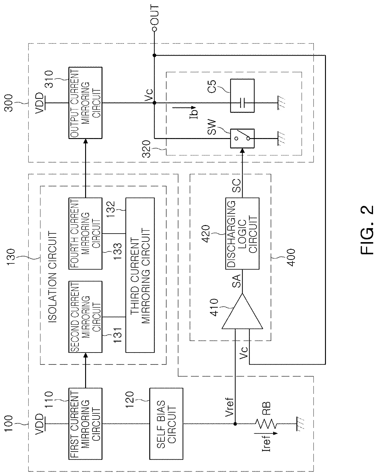
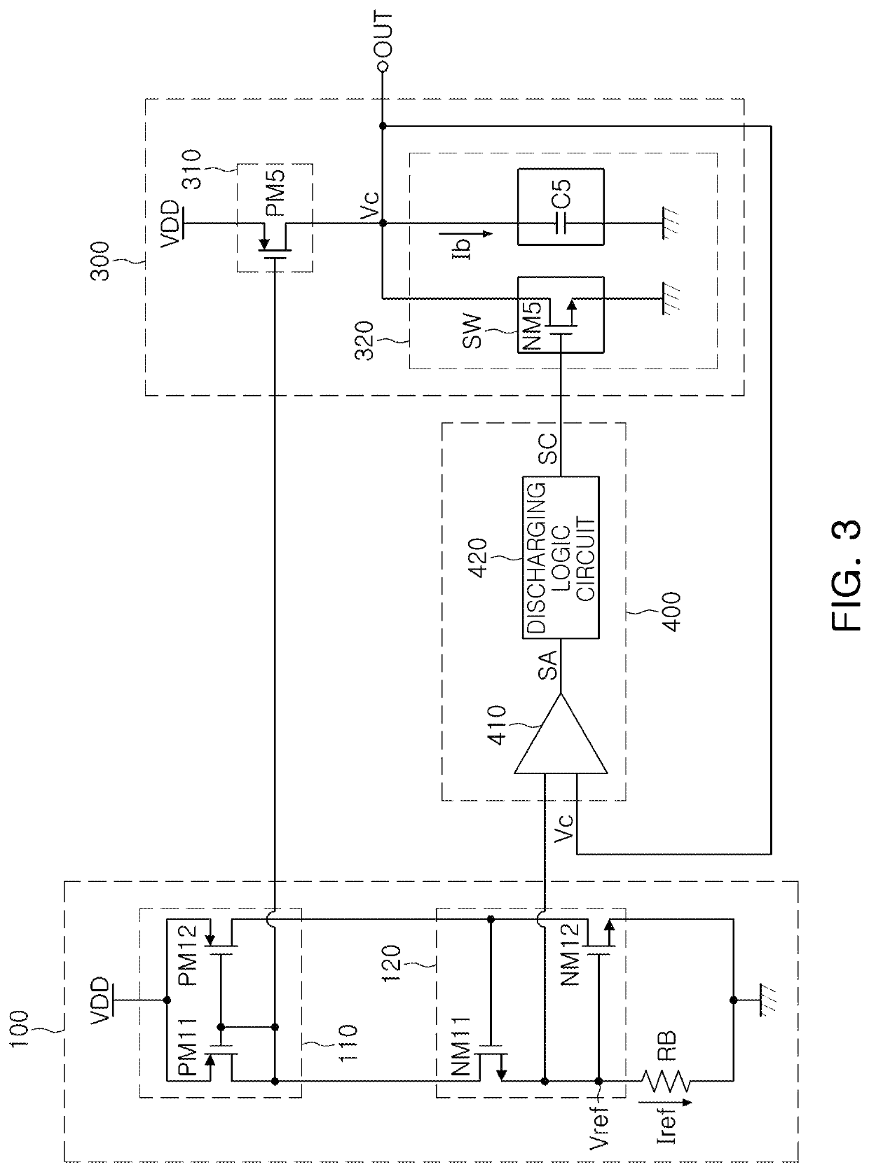
[0019]The bias circuit may include a first current mirroring circuit, a self-bias circuit, a bias resistor, and an isolation circuit. The first current mirroring circuit, including a first PMOS and a second PMOS connected to each other in a current mirroring structure, may be configured to generate the reference current. The self-bias circuit, including a first NMOS and a second NMOS connected to the first current mirroring circuit, may have a gate-sour

Problems solved by technology

When the voltage and the current vary with temperature, the period of the oscillation signal may change based on the changes in temperature, which may make the oscillation signal become unstable.
However, such a

Method used


Image

  • Oscillator circuit resistant to noise and jitter
  • Oscillator circuit resistant to noise and jitter
  • Oscillator circuit resistant to noise and jitter

Examples


Example

[0034]Throughout the drawings and the detailed description, the same reference numerals refer to the same elements. The drawings may not be to scale, and the relative size, proportions, and depiction of elements in the drawings may be exaggerated for clarity, illustration, and convenience.

DETAILED DESCRIPTION

[0035]The following detailed description is provided to assist the reader in gaining a comprehensive understanding of the methods, apparatuses, and / or systems described herein. However, various changes, modifications, and equivalents of the methods, apparatuses, and / or systems described herein will be apparent after an understanding of the disclosure of this application. For example, the sequences of operations described herein are merely examples, and are not limited to those set forth herein, but may be changed as will be apparent after an understanding of the disclosure of this application, with the exception of operations necessarily occurring in a certain order. Also, descr...


PUM


Abstract

An oscillator circuit includes a bias circuit, a signal generation circuit, and a control circuit. The bias circuit is configured to generate a reference voltage based on a reference current and a bias resistor. The signal generation circuit is configured to generate a bias current based on the reference current, perform charging and discharging of a capacitor using the bias current, and generate an oscillation signal based on the charging and the discharging of the capacitor. The control circuit is configured to generate a control signal having a constant discharging time, based on the reference voltage and the oscillation signal, controlling the charging and the discharging of the capacitor.

Description

CROSS-REFERENCE TO RELATED APPLICATION(S)[0001]This application claims the benefit under 35 USC 119(a) of Korean Patent Application No. 10-2020-0006575 filed on Jan. 17, 2020, in the Korean Intellectual Property Office, the entire disclosure of which is incorporated herein by reference for all purposes.BACKGROUND1. Field[0002]The present disclosure relates to an oscillator circuit resistant to low noise and jitter.2. Description of Related Art[0003]In general, an oscillator circuit generates an oscillation signal having a period. Here, the period may be determined depending on a voltage or a current. When the voltage and the current vary with temperature, the period of the oscillation signal may change based on the changes in temperature, which may make the oscillation signal become unstable.[0004]For example, in a conventional oscillator circuit having a band gap reference (BGR) circuit, the frequency of an oscillation signal, which is a period, is ‘T=CV / I’. The band gap reference ...

Claims


Application Information

Patent Timeline
IPC IPC(8): H03K3/013H03K3/011H03K4/502H03K3/0231
CPCH03K3/013H03K3/011H03K3/0231H03K4/502H03B5/04H03B5/24H03K3/57H03K5/135
Inventor LIM, TAE HO
Owner SAMSUNG ELECTRO MECHANICS CO LTD
Why Eureka
Try Eureka