
Deformable polymer membranes

a polymer membrane and microfluidic technology, applied in the direction of machines/engines, flexible member pumps, positive displacement liquid engines, etc., can solve the problems of significant device failure rate, difficult to integrate different microfluidic components into a single chip,

Inactive Publication Date: 2006-04-06
INTEL CORP
View PDF15 Cites 43 Cited by
  • Summary
  • Abstract
  • Description
  • Claims
  • Application Information

AI Technical Summary

Problems solved by technology

However it has not been easy to integrate different microfluidic components together into a single chip.
This has been due to the different and sometimes difficult fabrication requirements for each of the microfluidic components.
Essential processes such as bonding, aligning, clamping and interconnections for realizing a micro total analysis system generally cause significant device failure rates.

Method used


Image

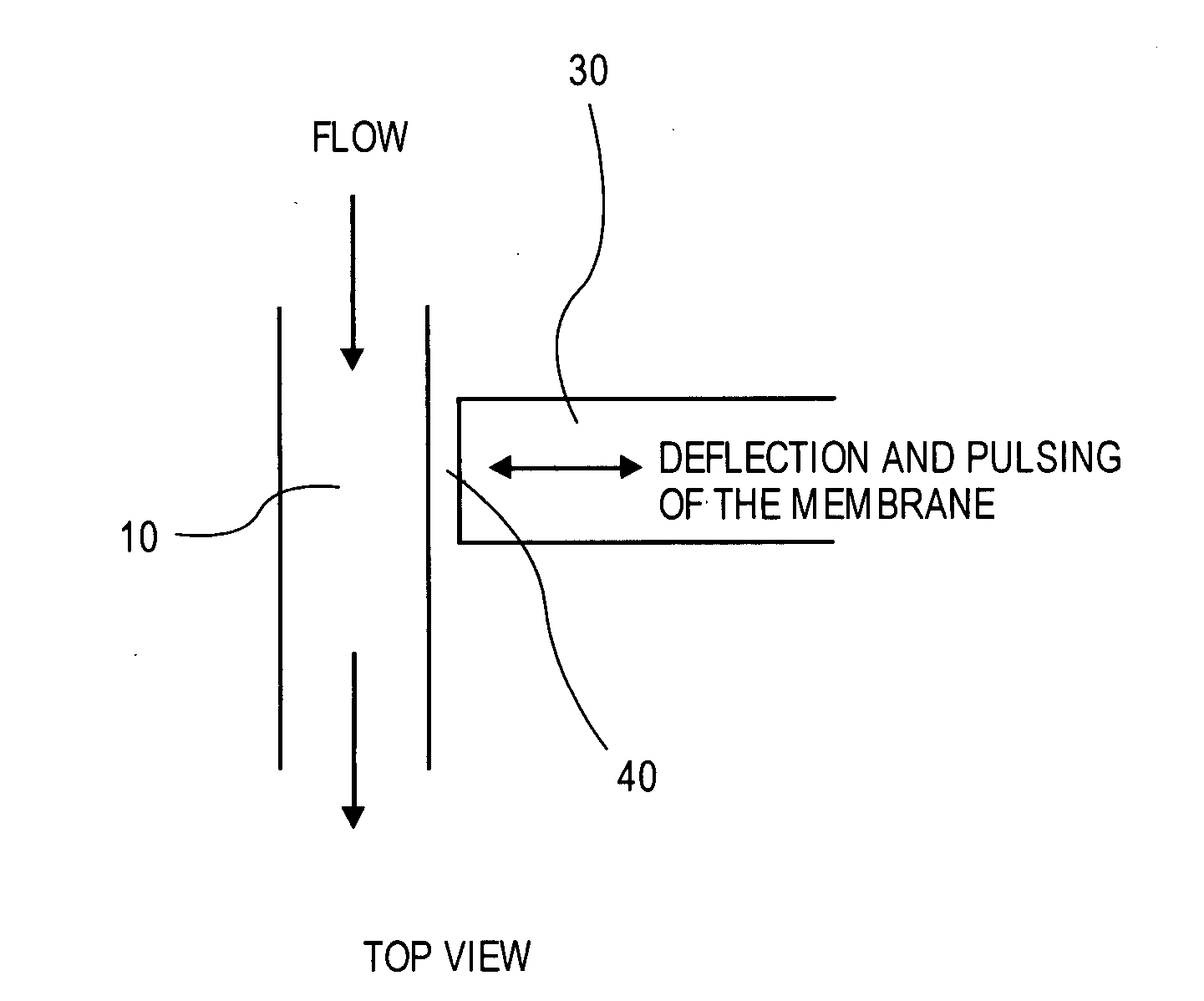
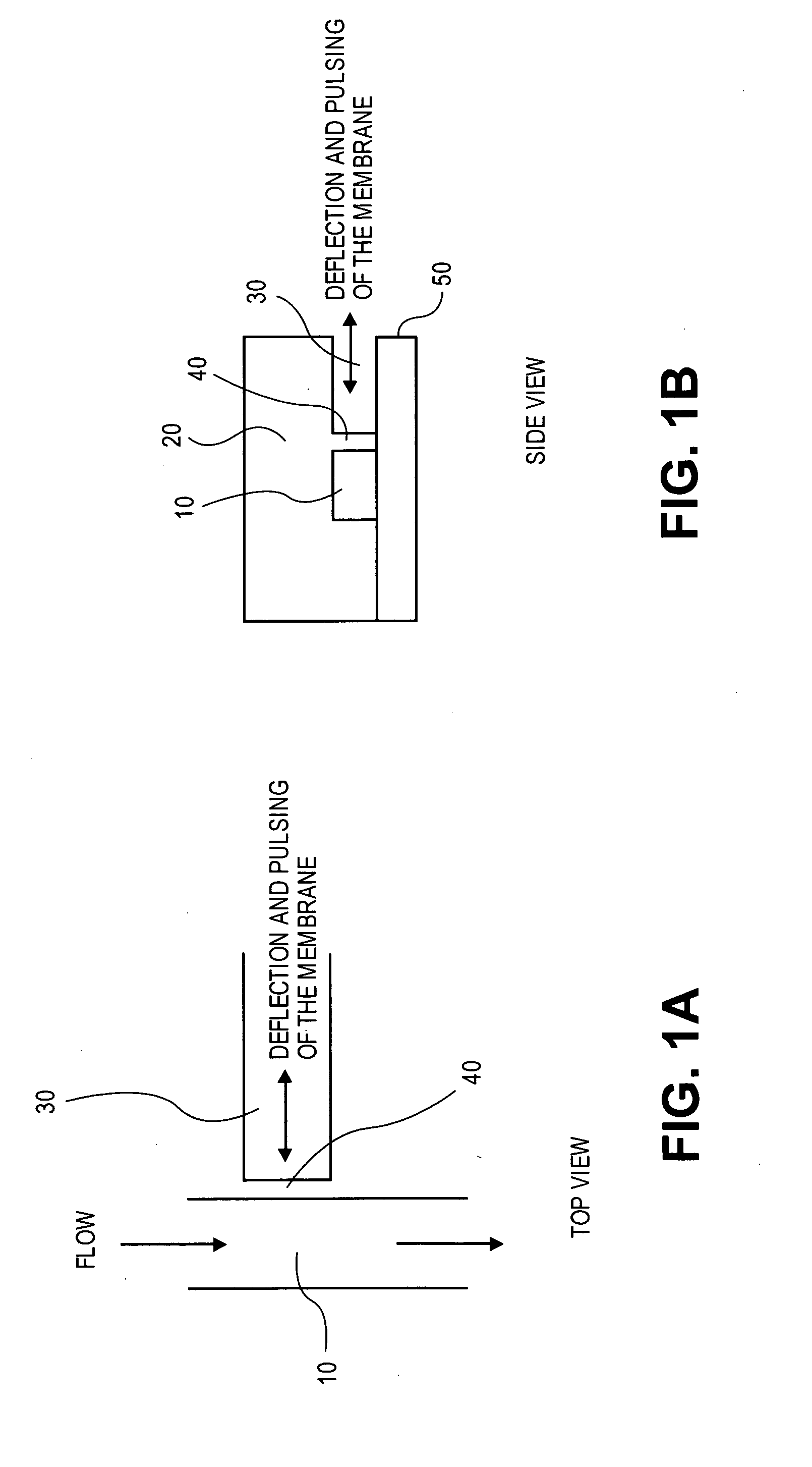
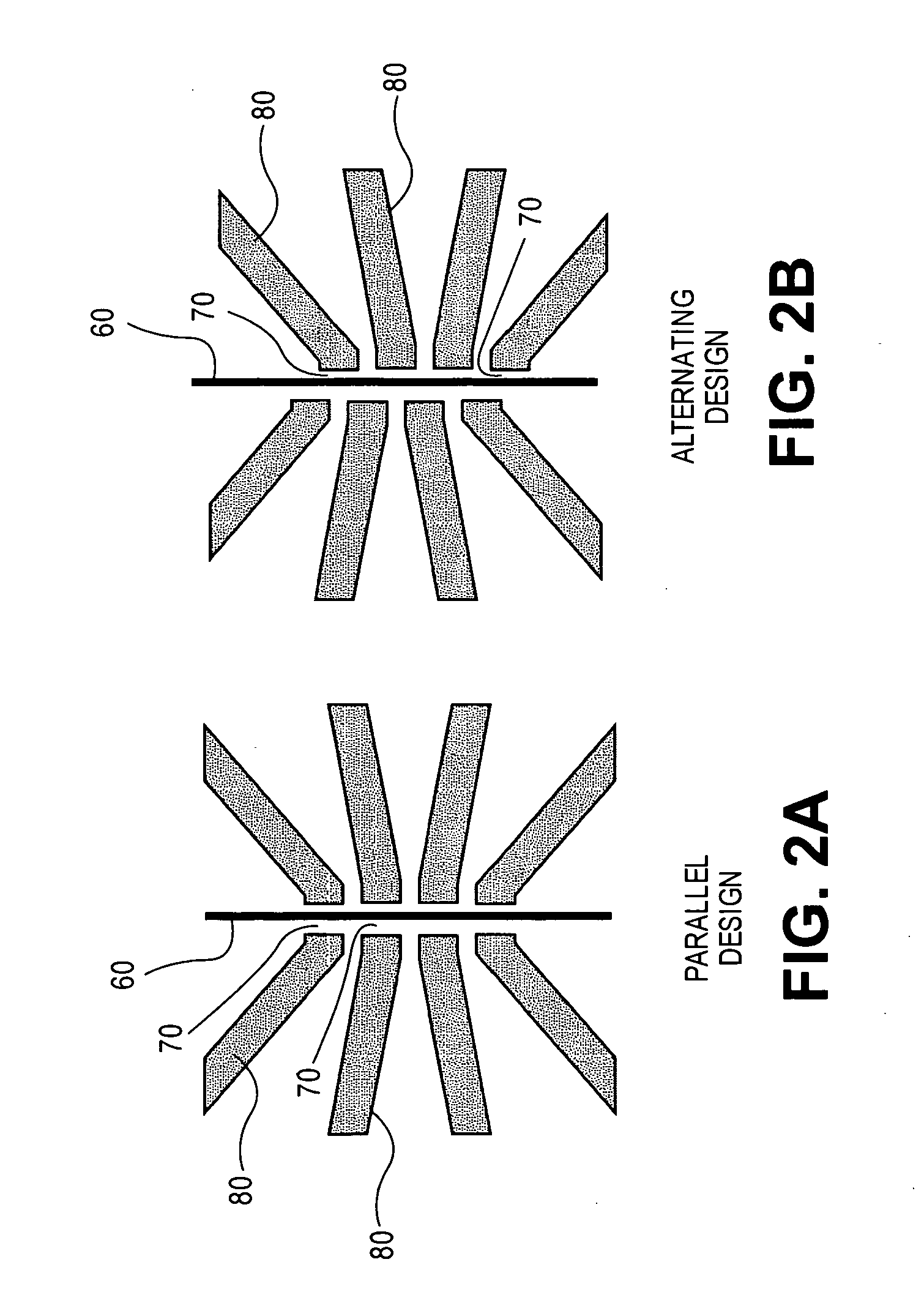
  • Deformable polymer membranes
  • Deformable polymer membranes
  • Deformable polymer membranes

Examples


examples

[0043] Precursors for poly(dimethyl siloxane), Sylgard A and B were obtained from Dow Corning Inc. 1 and 6 μm YG fluorescent poly(styrene) beads used to visualize flow were obtained from Polysciences Inc. SU-2035 Photoresist was obtained from Microchem Corp.

[0044] An actuation system consisting of hardware and software components was constructed for pneumatically controlling the operating channels. Referring to FIG. 14, the actuation system consisted of a control computer 440 generating a programmed actuating pattern that is converted into a control signal through a digital output board (NI MIO-16XE-10, National Instruments) 450. The control signal operates the valve drive (NI SCCDO01, National Instruments) 460 that converts the control signals into the appropriate power leveled operating power patterns for switching the solenoid valves (LHDA1223111H, Lee company) 470. Regulated external gas pressures (10-30 psi) were provided to the normally closed port of the manifold on which th...


PUM


Abstract

Embodiments of the present invention provide microfluidic devices containing deformable polymer membranes. The devices can be fabricated from a single polymeric block. Actuation of the membranes within the device allows the fluid contained within a microfluidic channel to be manipulated. Exemplary microfluidic devices, such as, peristaltic pumps, sample sorters, and mixers are described.

Description

CROSS-REFERENCE TO RELATED APPLICATION [0001] The present application claims the benefit under 35 U.S.C. § 119(e) of U.S. Provisional Patent Application No. 60 / 615,525, filed Sep. 30, 2004, the disclosure of which is incorporated herein by reference.BACKGROUND OF THE INVENTION [0002] 1. Field of the Invention [0003] Embodiments of the present invention relate generally to microfluidic operations and deformable polymer membranes. [0004] 2. Background Information [0005] Microfluidic components for performing a variety of operations are integral parts of micro-total analysis system applications. For example, cell sorters have become a vital component in micro total analysis systems aiming to investigate biological events at the single cell level. However it has not been easy to integrate different microfluidic components together into a single chip. This has been due to the different and sometimes difficult fabrication requirements for each of the microfluidic components. For example, ...

Claims


Application Information

Patent Timeline
Patent Type & Authority Applications(United States)
IPC IPC(8): F04B43/00
CPCF04B43/043
Inventor SUNDARARAJAN, NARAYAN
Owner INTEL CORP
Features
  • Generate Ideas
  • Intellectual Property
  • Life Sciences
  • Materials
  • Tech Scout
  • Unparalleled Data Quality
  • Higher Quality Content
  • 60% Fewer Hallucinations
Learn More