Spinal fixation tool set and method for rod reduction and fastener insertion

a technology of fixation tool set and rod, which is applied in the field of spinal fixation tool set and method for rod reduction and fastener insertion, can solve the problems of additional trauma or damage to patients, oversized tools, and bulky tools, and achieves the effects of low profile, easy and readily attached to and disengaged from bone screws, and easy alignment, positioning and engagemen

Active Publication Date: 2006-04-06
JACKSON
View PDF52 Cites 333 Cited by
  • Summary
  • Abstract
  • Description
  • Claims
  • Application Information

AI Technical Summary

Problems solved by technology

Problems arise when implantation tools designed for traditional surgery that is highly invasive are utilized.
The tools may be bulky, oversized or have irregular surfaces or protrusions.
A projecting actuator arm or fastening member may provide adequate mechanical advantage to force a rod into a head of an implant, but there may be insufficient clearance to use such structure and / or such structure may produce additional trauma or damage to the patient.

Method used


Image

  • Spinal fixation tool set and method for rod reduction and fastener insertion
  • Spinal fixation tool set and method for rod reduction and fastener insertion
  • Spinal fixation tool set and method for rod reduction and fastener insertion

Examples


Embodiment Construction

[0038] As required, detailed embodiments of the present invention are disclosed herein; however, it is to be understood that the disclosed embodiments are merely exemplary of the invention, which may be embodied in various forms. Therefore, specific structural and functional details disclosed herein are not to be interpreted as limiting, but merely as a basis for the claims and as a representative basis for teaching one skilled in the art to variously employ the present invention in virtually any appropriately detailed structure.

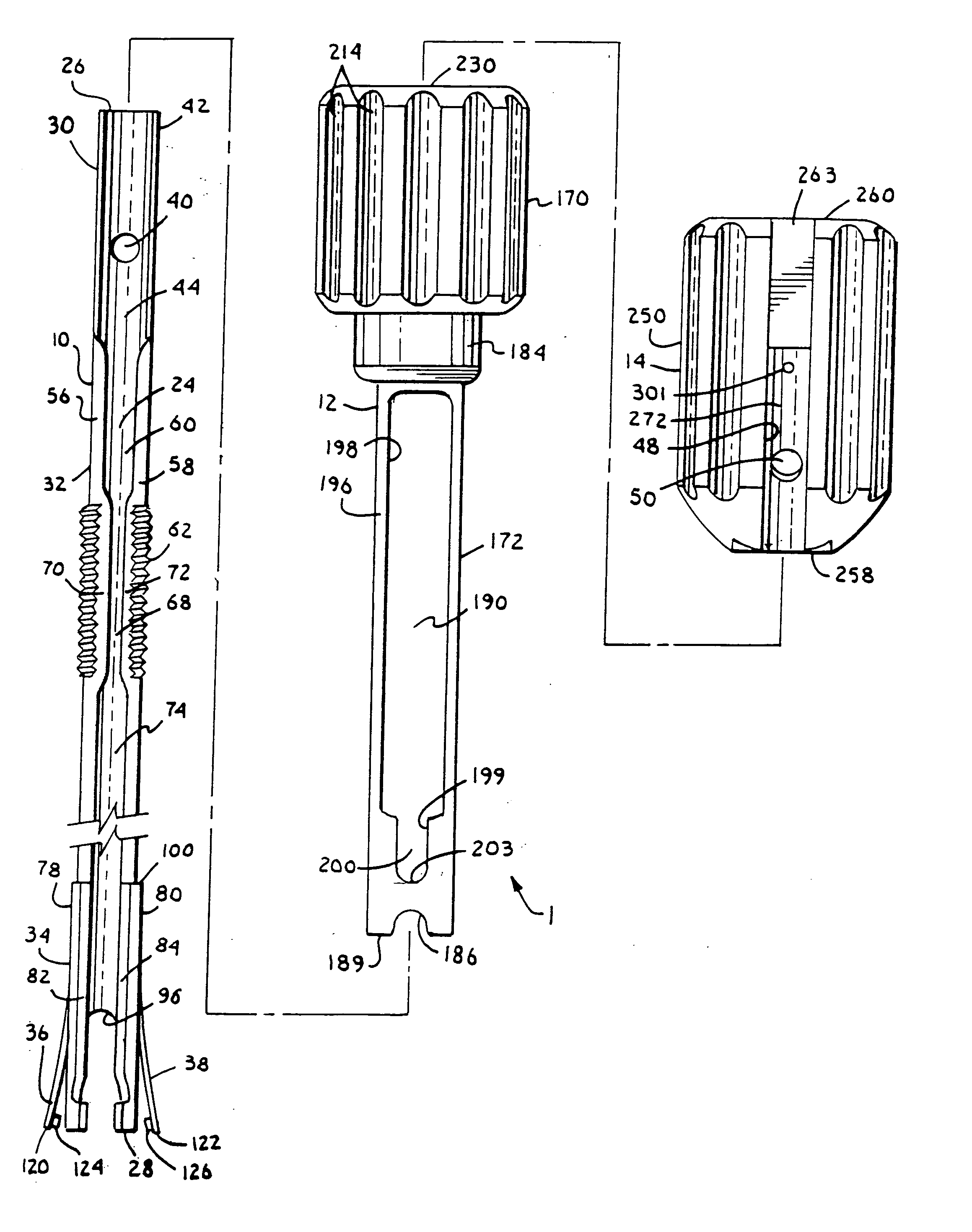
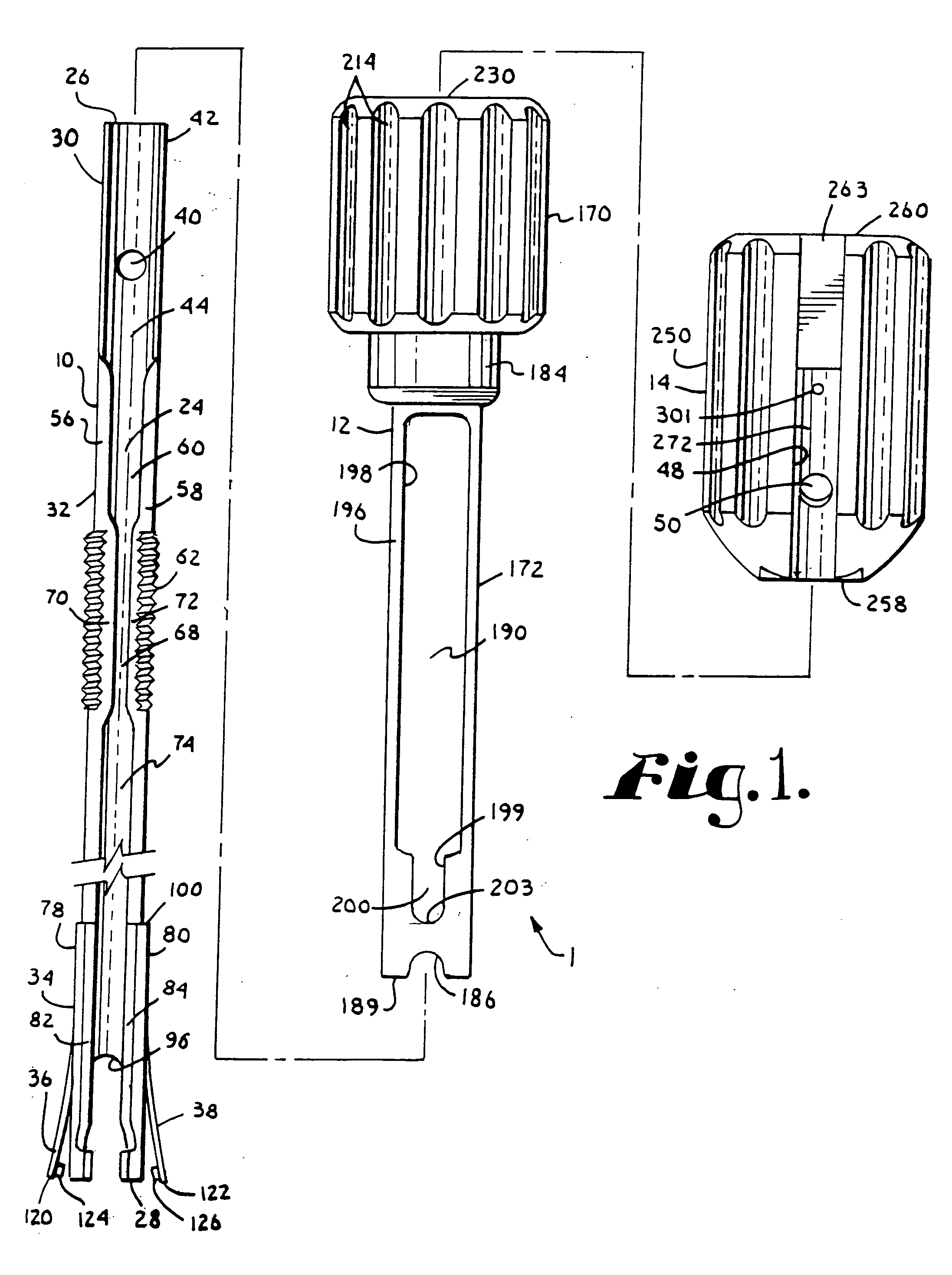
[0039] With reference to FIG. 1, reference numeral 1 generally designates a tool assembly according to the present invention, including a guide structure or member 10 configured for releaseable attachment to a bone screw, attachable to a rod pushing member 12 configured to function as an installation tool that not only pushes or reduces a rod into a bone screw but also presses the guide member into contact and attachment with the bone screw. Also attachable...


PUM


Abstract

A tool for implantation of a rod into a bone screw implanted in a human spine includes a guide member having a laterally opening channel disposed along an entire length thereof for side loading and receiving an implant fastener. A rod pushing member and a handle with a laterally opening channel are coaxial with the guide member, with the rod pushing member being rotatingly mateable to the guide member and the handle having a spring attachment mechanism for attaching the handle to the guide member. The guide member includes spring tabs for attachment to a bone screw, the tabs biased away from the bone screw. The rod pushing member includes a sleeve that extends substantially about the guide member, pressing the spring tabs toward the bone screw and into apertures on the bone screw arms. The rod pushing member sleeve also operatively functions as a rod pusher that abuts a rod as the sleeve is translated along the guide member and toward the bone screw. The handle lateral opening receives and supports a manipulation tool for inserting and installing an implant fastener for attaching the rod to the bone screw.

Description

BACKGROUND OF THE INVENTION [0001] The present invention relates to apparatuses and methods for use in performing spinal surgery and, in particular, to tools and methods of using such tools, especially for implanting a rod for spinal support and alignment. [0002] For many years, spinal osteosynthesis apparatuses have been utilized to correct spinal deformities, injuries or disease. In such procedures, elongate rods are surgically attached to vertebrae of the spine to provide support and / or to realign or reposition certain vertebrae. Such rods are secured to vertebrae utilizing bone screws and other spinal implants. In particular, bone screws with open ended heads are often utilized for such surgery, with the rod being placed into an open end of one or more implants and then the open end or ends being closed or capped to secure the rod to the implant. [0003] Rods utilized in spinal surgery are often bent or formed to support the spine in a desired manner, or to exert a desired correc...

Claims


Application Information

Patent Timeline
Patent Type & Authority Applications(United States)
IPC IPC(8): A61F2/30
CPCA61B17/7086A61B17/7091A61B2019/307A61B2090/037
Inventor JACKSON, ROGER P.
Owner JACKSON
Why Eureka
Try Eureka