Fixation augmentation device and related techniques

a fixation device and fixation technology, applied in the field of surgical fasteners, can solve the problems that cannot be achieved with a round collar, and achieve the effects of enhancing fixation, improving screw purchase, and enhancing fixation

Inactive Publication Date: 2006-04-06
SIMPLICITY ORTHOPEDICS
View PDF37 Cites 105 Cited by
  • Summary
  • Abstract
  • Description
  • Claims
  • Application Information

AI Technical Summary

Benefits of technology

[0011] In accordance with the present invention, a Fixation Augmentation Device (FAD) includes a tubular body or sleeve having a collar disposed on a first end thereof. The sleeve is provided having an outside diameter selected such that the sleeve fits into a hole drilled in a bone. The collar at the first or proximal end of the sleeve prevents advancement of the FAD into the hole with screw insertion. With this particular arrangement, a device that allows a surgeon to quickly remove a “spinner” screw and reinsert the screw in a manner such that a screw which obtains adequate purchase is provided. Furthermore by utilizing the FAD the originally selected angle of the screw relative to the fracture is maintained. The FAD improves screw purchase by effectively restoring the appropriate si...

Problems solved by technology

This would not be acco...

Method used


Image

  • Fixation augmentation device and related techniques
  • Fixation augmentation device and related techniques
  • Fixation augmentation device and related techniques

Examples


second embodiment

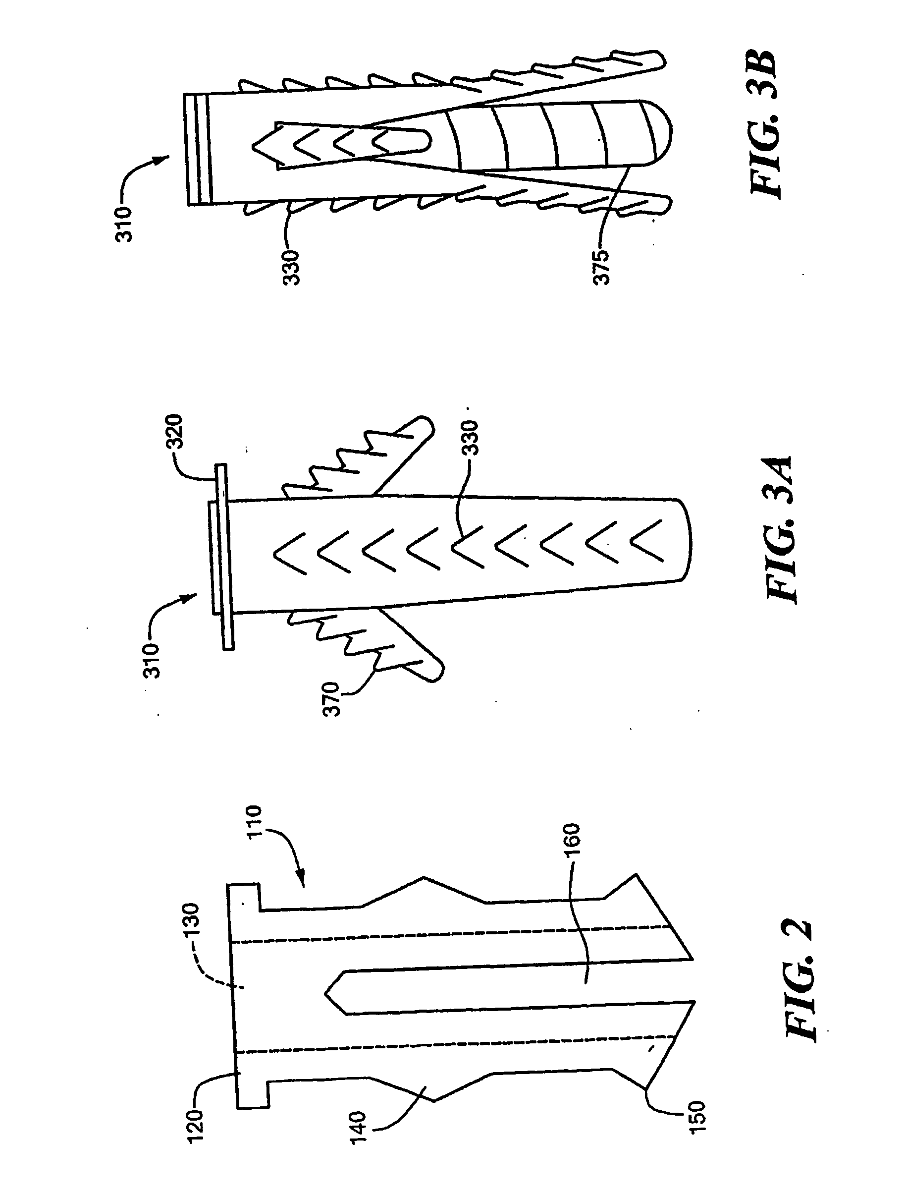
[0080] a FAD 110, is shown in FIG. 2. The FAD 110 has a similar structure as FAD 10. FAD 110 includes a collar 120, a core 130, an interference region 140, a flange portion 150 and a slot 160. Operation of FAD 110 is similar to the operation of FAD 10 described above. FAD 110 clips into place in a bone hole. Slot 160 allows for the ends of the FAD to adequately clip into place.

embodiment 310

[0081] Referring now to FIGS. 3A-B, another embodiment 310 of a FAD is shown. In this embodiment the interference region is provided having a plurality of ridges or teeth 330 on an outer surface thereof. The ridges 330 help secure the FAD within the bone hole. FAD 310 further includes wings 370 in the interference region which expand in response to a screw passing through the interference region and which secure the FAD within the bone hole. The outer walls of the FAD 310 can be ribbed, threaded or fretted to enhance the fixation of the device within the bone hole. Further the outer surface of the collar can also be ribbed, threaded or fretted to enhance the fixation of the device. As shown in to FIG. 3B, the interference region includes wings 375 in an end portion thereof which expand in response to a screw passing through the interference region such that when the wings are deployed, the wings engage an outer surface of the bone and increase the pull force required to remove the F...

fourth embodiment

[0101] Referring now to FIGS. 13A-13D, a FAD 1370 is shown. FAD 1370 includes a tubular body or sleeve 1372. The sleeve 1372 has a collar 1374 disposed on a first end thereof. Collar 1374 preferably has a generally oval shape that prevents rotation of the device when inserted into a bone plate or to allow a surface for a tool to use during the insertion of the device or during insertion of a screw into the device. A generally oval shoulder section 1384 is shown extending from the collar 1374. Shoulder 1384 has a tapered outer wall surface 1384a (FIG. 13D) and a tapered inner wall surface 1384b. FAD 1370 is preferably used with a bone plate, wherein the collar 1374 extends through a hole in the bone plate while shoulder 1384 extends into and engages an inner surface of the hole in the bone plate. The FAD 1370 is inserted into the bone plate hole and into the bone hole. When a screw is inserted into FAD core 1378, the FAD 1370 is securely engaged with the bone plate by way of shoulder...


PUM


Abstract

A Fixation Augmentation Device (FAD) is presented. The FAD includes a tubular body or sleeve (902) having a collar (904) disposed on a first end thereof. The sleeve is provided having an outside diameter selected such that the sleeve fits into a hole drilled in a bone. The collar at the first or proximal end of the sleeve prevents advancement of the FAD into the hole with screw insertion. Flanges (908) are provided at the distal portion of the sleeve to provide interference fixation of the FAD to the bone, thereby allowing the screw and FAD to obtain purchase where a screw alone would have failed or otherwise have inadequate fixation. The FAD is also designed to collapse as it is withdrawn from the drill hole in the event of removal of the device is desired.

Description

CROSS REFERENCE TO RELATED APPLICATIONS [0001] This application claims the benefit of PCT Application No. PCT / US2004 / 014640 filed on May 10, 2004 which claims the benefit of provisional patent application Ser. No. 60 / 468,829 filed May 8, 2003, the disclosure of which is incorporated herein by reference and this application is a continuation-in-part (CIP) of patent application Ser. No. 10 / 246,304 filed on Sep. 18, 2002, which claims the benefit of provisional patent application Ser. Nos. 60 / 323,347 filed on Sep. 18, 2001, 60 / 347,212 filed on Jan. 10, 2002, and 60 / 374,534 filed on Apr. 22, 2002 the disclosures of which are each incorporated herein by reference.STATEMENT REGARDING FEDERALLY SPONSORED RESEARCH [0002] Not Applicable FIELD OF THE INVENTION [0003] The present invention relates generally to surgical fasteners. More particularly, the present invention relates to a mounting or anchoring device for use with a screw or bone being fastened to a bone or other body structure. BACK...

Claims


Application Information

Patent Timeline
IPC IPC(8): A61B17/58A61B17/68A61B17/80
CPCA61B17/686A61B17/80A61B17/8052
Inventor BICKLEY, BARRY T.ZOVICH, ALDO M.ZOVICH, RICHARD E.
Owner SIMPLICITY ORTHOPEDICS
Why Eureka
Try Eureka