Communication bandwidth control method for a broadcast communication system, a server and a user terminal used in a broadcast communication system, and a program

a communication system and communication bandwidth technology, applied in the field of broadcast communication systems, can solve the problems of limited communication bandwidth for transmitting and receiving data, deterioration of voice communication quality, and unused communication bandwidth reserved for data that is not transmitted, so as to prevent deterioration in voice communication by transmission and reception of other data communications, effective control of available communication bandwidth, and effective use of limited communication bandwidth

Inactive Publication Date: 2006-04-06
FUJITSU LTD
View PDF9 Cites 11 Cited by
  • Summary
  • Abstract
  • Description
  • Claims
  • Application Information

AI Technical Summary

Benefits of technology

[0009] According to an aspect of the present invention a plurality of users conduct broadcast communications using a common conference room formed on the network, transmitting and receiving voice data and data other than the voice data. Deterioration in a quality of voice communication by a transmission and reception of the other data communications is prevented, and the limited communication bandwidth is used effectively. The quality of data, such as voice data and picture data, required to have realtime properties is influenced by the communication bandwidth both on the transmitting side and receiving side when such data is obtained and reproduced through communication. Moreover, the communication bandwidth varies according to a kind of network connecting the user terminals. Even when a plurality of user terminals of different available communication bandwidths are connected, means are provided to control the communication bandwidth so that the available communication bandwidth is effectively controlled.

Problems solved by technology

However, the communication bandwidth for transmitting and receiving of the data is limited, particularly in the use of cellular phones.
If voice and data communications other than voice are transmitted and received in combination, a delay and a fluctuation of the voice data are increased, resulting in a deterioration of a quality of the voice communication received.
Thus, communication bandwidth reserved for data that is not transmitted is left unused, and thereby the available communication bandwidth is not used effectively.
Thus, a problem exists that such conventional methods are inefficient in use of bandwidth.
However, a problem still exists with such methods in that use of bandwidths is inefficient.

Method used


Image

  • Communication bandwidth control method for a broadcast communication system, a server and a user terminal used in a broadcast communication system, and a program
  • Communication bandwidth control method for a broadcast communication system, a server and a user terminal used in a broadcast communication system, and a program
  • Communication bandwidth control method for a broadcast communication system, a server and a user terminal used in a broadcast communication system, and a program

Examples


second embodiment

[0128] According to the present invention, an example of a control in the server side for the communication bandwidth for transmission of data other than the voice data will be described.

[0129]FIG. 11 is a block diagram illustrating a second embodiment.

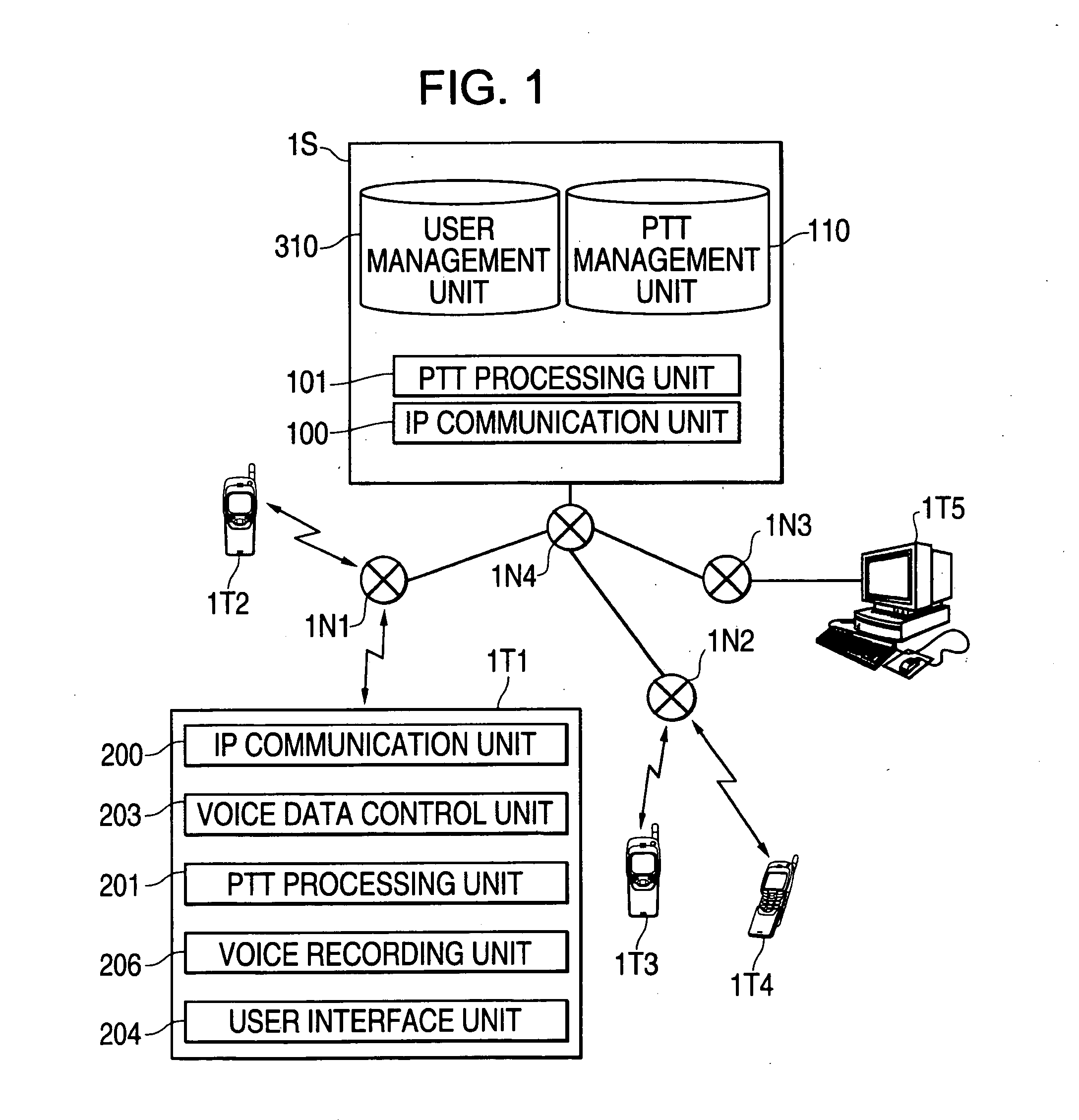
[0130] A server 3S for controlling the broadcast communication among a plurality of terminals and a plurality of terminals 3T1, 3T2, 3T3, 3T4, . . . (hereinafter a terminal is generally called a “terminal 3T” in some cases) are provided for communications via various networks 3N1, 3N2 . . . hereinafter a network is generally called a “network 3N” in some cases). For example, it is assumed that a network 3N1 is a cellular phone communication network provided by the cellular phone company A and the communication system is a CDMA 1× system, while the network 3N2 is the cellular phone communication network provided by the cellular phone company B and the communication system is the PHS system. The network 2N3 is a wired network such as a...

third embodiment

[0166] Next, an example flow of processes for controlling communication bandwidth in an example the third embodiment will be described with reference to FIG. 19. Procedures after the terminal 2T has requested the data transmission right will be described.

[0167] The terminal 2T conducts the following determination for the other terminals participating in the same conference room so as to calculate a value that may be used in reception of the data with the down-stream communication bandwidth of respective terminals 2T.

[0168] The terminal 2T determines whether the data transmission right has been acquired. When the data transmission right is acquired (Yes in 19010 illustrated in FIG. 19), a communication bandwidth for transmission of data is calculated using the following example procedures for each terminal 2T designated as a partner in the data transmission.

[0169] Whether the terminal 2T, as the partner of the data transmission, is registered as the partner 182 of voice is determin...


PUM


Abstract

A method transmitting and receiving data other than voice data and preventing deterioration in quality of communication voice data due to transmission and reception of the other than voice data, and utilizing a limited communication bandwidth when a plurality of users conduct the broadcast communication through common use of the conference room on the network. Upon a user terminal transmitting second data, verifying whether any of a plurality of identified user terminals has a right of transmission of first data. The method further includes that upon a user terminal having the a transmission right of first data, setting a value obtained by subtracting the communication bandwidth required for transmission of the first data from the communication bandwidth which each user terminal can use as the communication bandwidth for transmission of the second data. Upon no user terminal having a transmission right of first data, setting a communication bandwidth that each user terminal can use as the communication bandwidth for transmission of the second data.

Description

CROSS-REFERENCE TO RELATED APPLICATIONS [0001] This application claims the benefit of Japanese Patent Application No. 2004-256066, filed on Sep. 2, 2004 in the Japanese Patent Office, the disclosure of which is incorporated herein by reference. BACKGROUND OF THE INVENTION [0002] 1. Field of the Invention [0003] The present invention relates to a broadcast communication system for communication through transmission and reception of data via a communication network among a plurality of user terminals, and particularly to a broadcast communication system for distributing received data to designated user terminals by accepting the data and designation of the data transmitting destination from any of the user terminals. [0004] A communication group which is virtually formed on the network for making broadcast communication among a plurality of user terminals is called a “conference room”. This conference room may have various profiles and forms a communication group with the communicatio...

Claims


Application Information

Patent Timeline
Patent Type & Authority Applications(United States)
IPC IPC(8): G06F15/173H04L12/18H04L47/2416H04M3/00
CPCH04L12/18H04L12/189H04L12/5695H04L47/15H04L47/801H04L47/806H04L47/808H04L47/822H04L47/824H04W28/20H04L47/70H04W72/0453
Inventor HORIO, KENICHIOHNO, TAKASHIOKUYAMA, SATOSHI
Owner FUJITSU LTD
Why Eureka
Try Eureka