
Assembly for attaching a detection unit, in particular for detecting tyre pressure, to a rim

a detection unit and assembly technology, applied in the field of detecting parameters, can solve the problems of unrespected control screwing, pressure loss and failure, and the presence of fixing nut at the exterior, so as to reduce the mass, prevent the screwing force applied, and reduce the stress

Active Publication Date: 2006-04-13
LDL TECH
View PDF8 Cites 24 Cited by
  • Summary
  • Abstract
  • Description
  • Claims
  • Application Information

AI Technical Summary

Benefits of technology

[0018] Thus, an objective of this research is to propose and assembly in which the seal between the valve and the rim is less subject to the tangential and radial forces caused by acceleration, rotation speed and the mass of the assembly and the unit.
[0037] To reduce the stresses that may be exerted on the assembly of the invention, and, in general, any valve to which a detection unit is connected, the applicant has conducted research on the unit in particular so as to make it lighter. This research led to the design of a unit that does not require the presence of a polymer material, thereby considerably reducing its mass.

Problems solved by technology

However, the lifetime of an elastomer sealing element which is not designed to withstand such stress is considerably reduced, leading to pressure loss and failure.
However, this controlled screwing is not always respected.
Moreover, insofar as the screwing force is performed as prescribed, the presence of the fixing nut at the exterior makes unintentional unscrewing very easy.
Although this assembly proposes a solution to one of the problems of the prior art, it retains the other disadvantages described above.
In addition, another disadvantage found in the prior art relates to the unit itself which, for reasons of sealing and holding the components that it receives in position, is conventionally filled with a plastic material that increases the weight of the unit and makes it impossible to recycle it.

Method used


Image

  • Assembly for attaching a detection unit, in particular for detecting tyre pressure, to a rim
  • Assembly for attaching a detection unit, in particular for detecting tyre pressure, to a rim
  • Assembly for attaching a detection unit, in particular for detecting tyre pressure, to a rim

Examples


Embodiment Construction

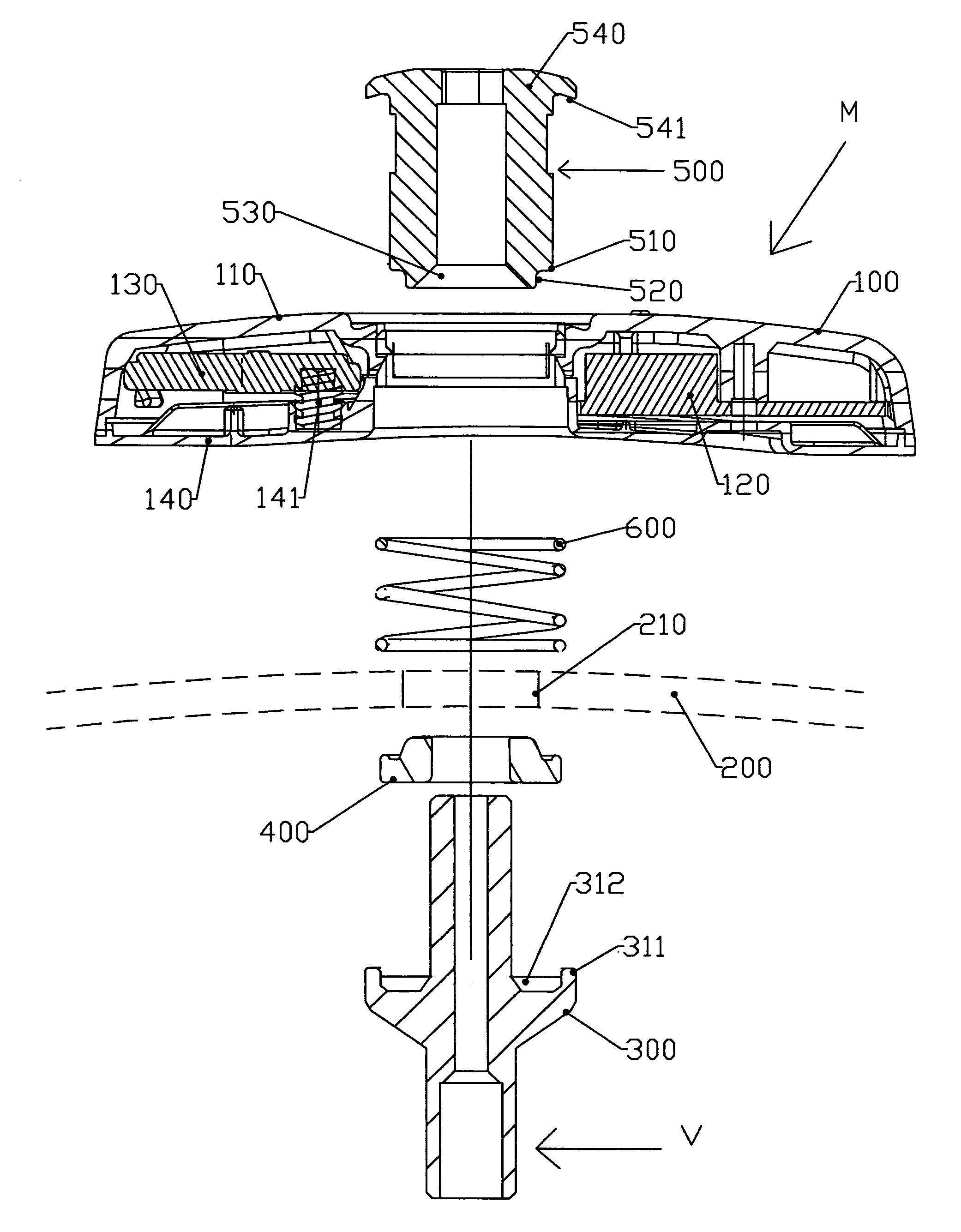
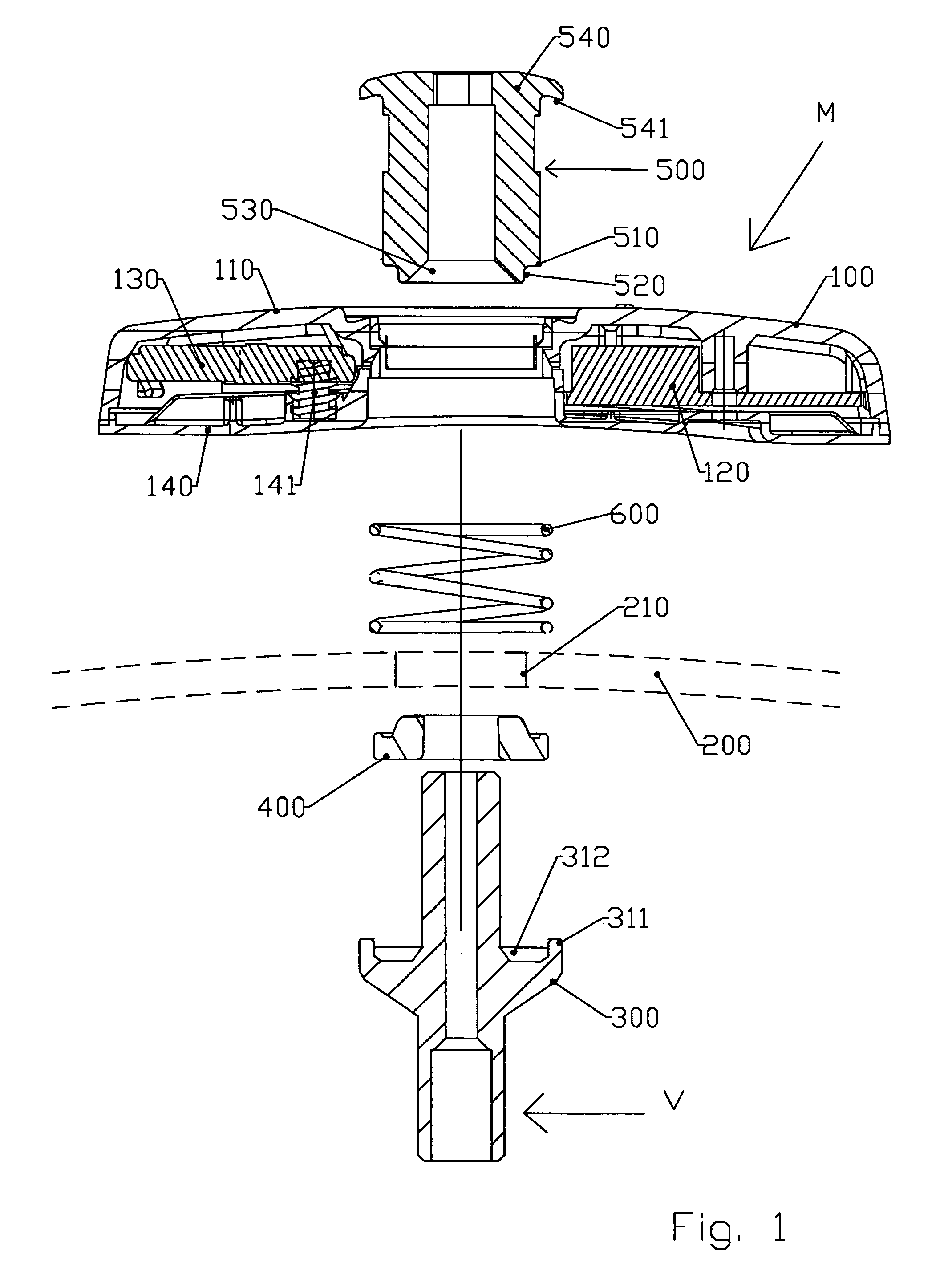
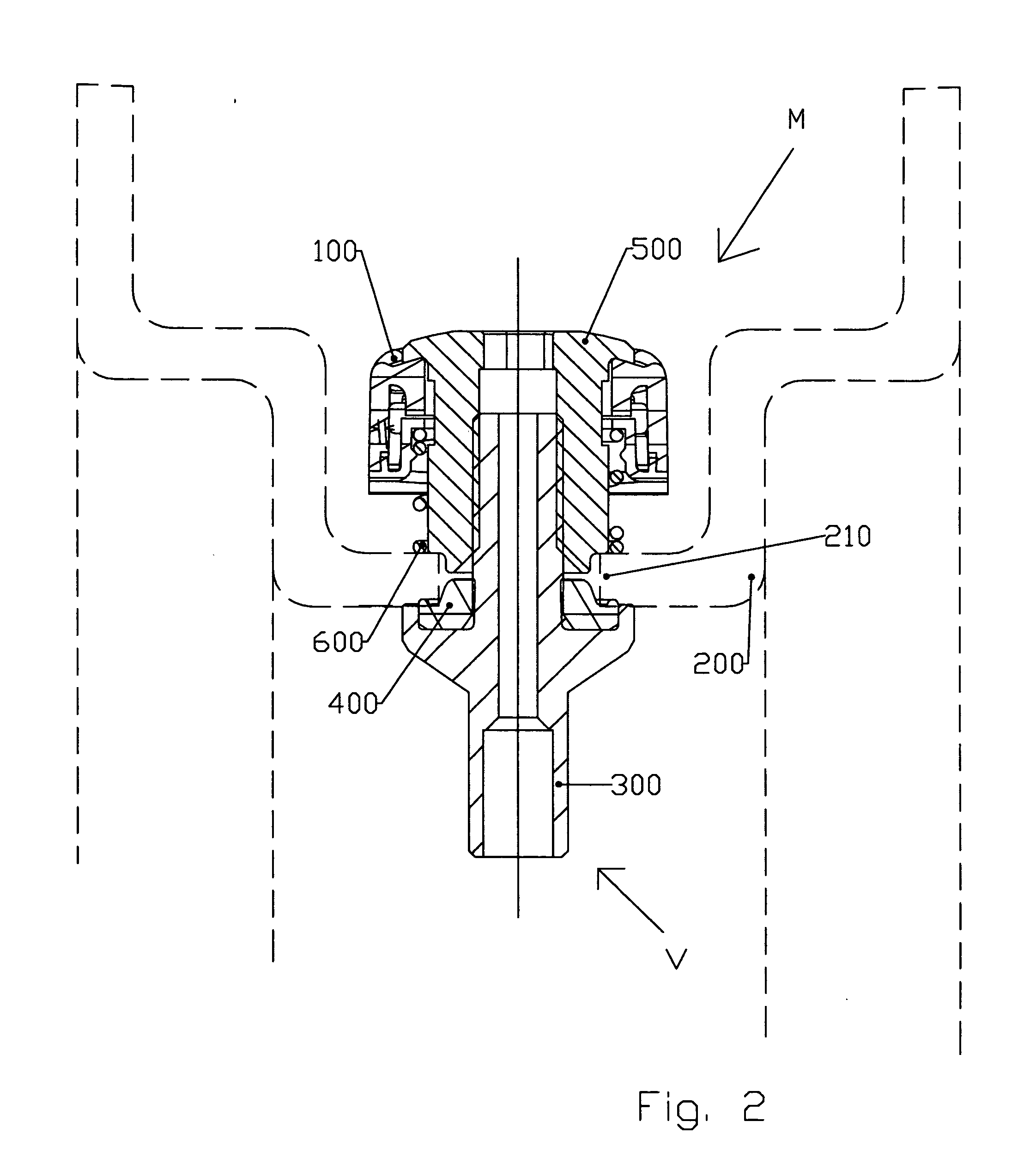
[0044] As shown in the drawing of FIGS. 1, 2 and 4, the assembly referenced M in its entirety of a detection unit 100 on a rim referenced 200 and represented by short broken lines is attached to the body 300 of a valve referenced V.

[0045] This assembly M includes the following elements:

[0046] a detection unit 100 receiving detection components and the elements necessary for their operation,

[0047] a valve body 300,

[0048] sealing means 400 providing a seal between the valve body 300 and the rim 200,

[0049] means 500 for holding the position of the valve body 300 on the rim 200 preformed with an aperture 210 allowing the valve body 300 to pass through,

[0050] a connection module, which, according to the embodiment shown, partially merges with the position holding means 500, for connecting the detection unit 100 to the valve body 300.

[0051] According to the invention, the assembly is remarkable in that the means 500 both holding the body 300 in position and connecting the body 300 ...


PUM


Abstract

The invention relates to an assembly (M) of a detection unit (100) inside a tyre which is attached to the body (300) of a valve (V) and including the following elements: a detection unit (100) receiving detection components, a valve body (300), sealing means (400) for providing a seal between the valve body (300) and the rim (200), means (500) for holding the valve body (300) in position on the rim (200) which is preformed with a connection aperture (210) provided for this purpose, a module for connecting the detection unit (100) to the valve body (300). This assembly is remarkable in that at least one of the elements (500) of said assembly, aside from the sealing means (400), is preformed so that a portion of this element (500) penetrates the connection aperture (210) so as to engage it when the assembly is subjected to tangential stresses.

Description

BACKGROUND OF THE INVENTION [0001] 1. Field of the Invention [0002] This invention relates to the field of detecting parameters such as the pressure or temperature inside a tyre, and more specifically to variations enabling the detection unit to be attached to the wheel rim under optimal conditions. [0003] 2. Related Art of the Invention [0004] There are several solutions in the prior art for attaching a detection unit. These solutions include the one adopted by the invention, which involves attaching, inside the rim, the detection unit which contains sensors corresponding to the parameters to be monitored, to the tyre inflation valve body. [0005] The applicant has noted that the implementations of this attachment solution known in the prior art have certain disadvantages, as described below. [0006] American documents U.S. Pat. No. 6,055,855 and U.S. Pat. No. 5,844,131 propose attaching a detection unit inside a tyre by means of a valve body, which involves an attachment assembly in...

Claims


Application Information

Patent Timeline
IPC IPC(8): B60C23/02
CPCB60C23/0408B60C23/0494B60C23/04B60C23/00
Inventor LUCE, DOMINIQUE
Owner LDL TECH
Learn More