Friction clutch assembly

a clutch assembly and friction technology, applied in the field of friction clutches, can solve the problems of inertia of the cover plate becoming a hindrance to racing performance, inertia of the cover plate increasing undesirably, and the event of the cover plate failing, so as to reduce the deflection of the cover plate, improve reliability, and reduce the effect of inertia

Inactive Publication Date: 2006-04-13
ACE MFG & PARTS
View PDF24 Cites 0 Cited by
  • Summary
  • Abstract
  • Description
  • Claims
  • Application Information

AI Technical Summary

Benefits of technology

[0008] Among the several objects and features of this invention may be noted the provision of a friction clutch assembly that reduces deflection of the cover; the provision of such a friction clutch assembly which has a long life; the provision of such a friction clutch assembly that is lightweight thus providing lower inertia; and the provision of such a friction clutch assembly that provides improved reliability and reduced clutch maintenance.
[0010] In another aspect of the invention a friction clutch assembly for connecting driving and driven shafts comprises a cover adapted for mounting on a flywheel of the driving shaft in a fixed axial position relative to the flywheel and for conjoint rotation with the flywheel. A pressure plate is supported by the cover for rotation therewith. The pressure plate is axially moveable between an engaged position wherein the pressure plate applies a force to clamp a friction disk of said driven shaft in operative engagement with the flywheel thereby to transmit torque from the driving shaft to the driven shaft and a disengaged position wherein the pressure plate does not clamp said friction disk and substantially no torque is transmitted to the driven shaft. A spring is in contact with the pressure plate whereby the spring urges the pressure plate into the engaged position and compression of the spring releases pressure on said pressure plate allowing for movement of said pressure plate to the disengaged position. The cover has a continuous curved surface to resist deflection and prevent premature failure of the cover. The continuous curved surface has a varying radius of curvature over a length of the curved surface.

Problems solved by technology

The cover plate deflection results in fatigue and eventual failure of the cover plate.
Increased size and weight of the cover plate undesirably increases its inertia.
The inertia of the cover plate becomes a hindrance to racing performance because of the energy from the engine taken up to maintain rotation of the cover plate detracts from the speed of the car.

Method used


Image

  • Friction clutch assembly
  • Friction clutch assembly
  • Friction clutch assembly

Examples


Embodiment Construction

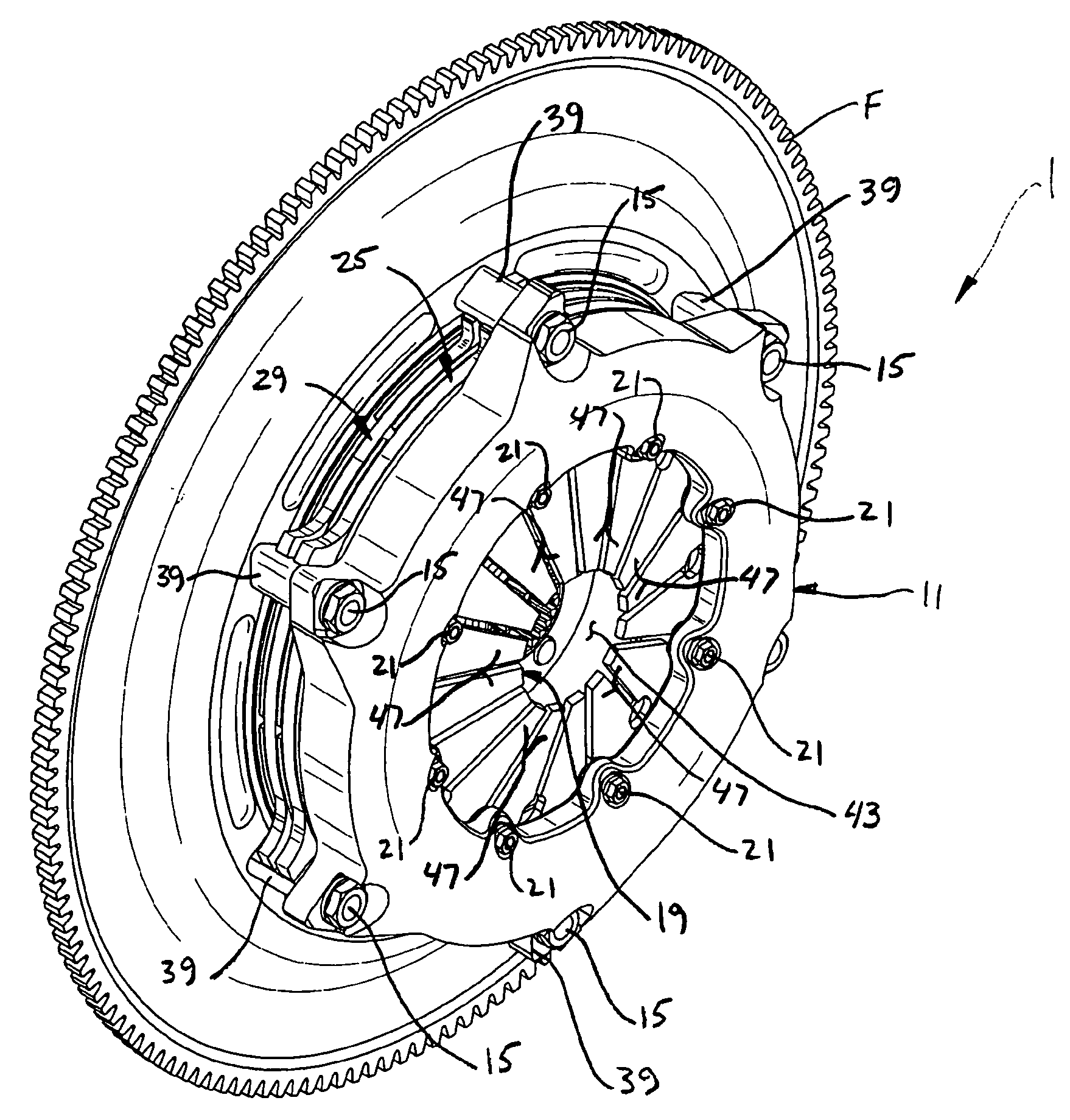
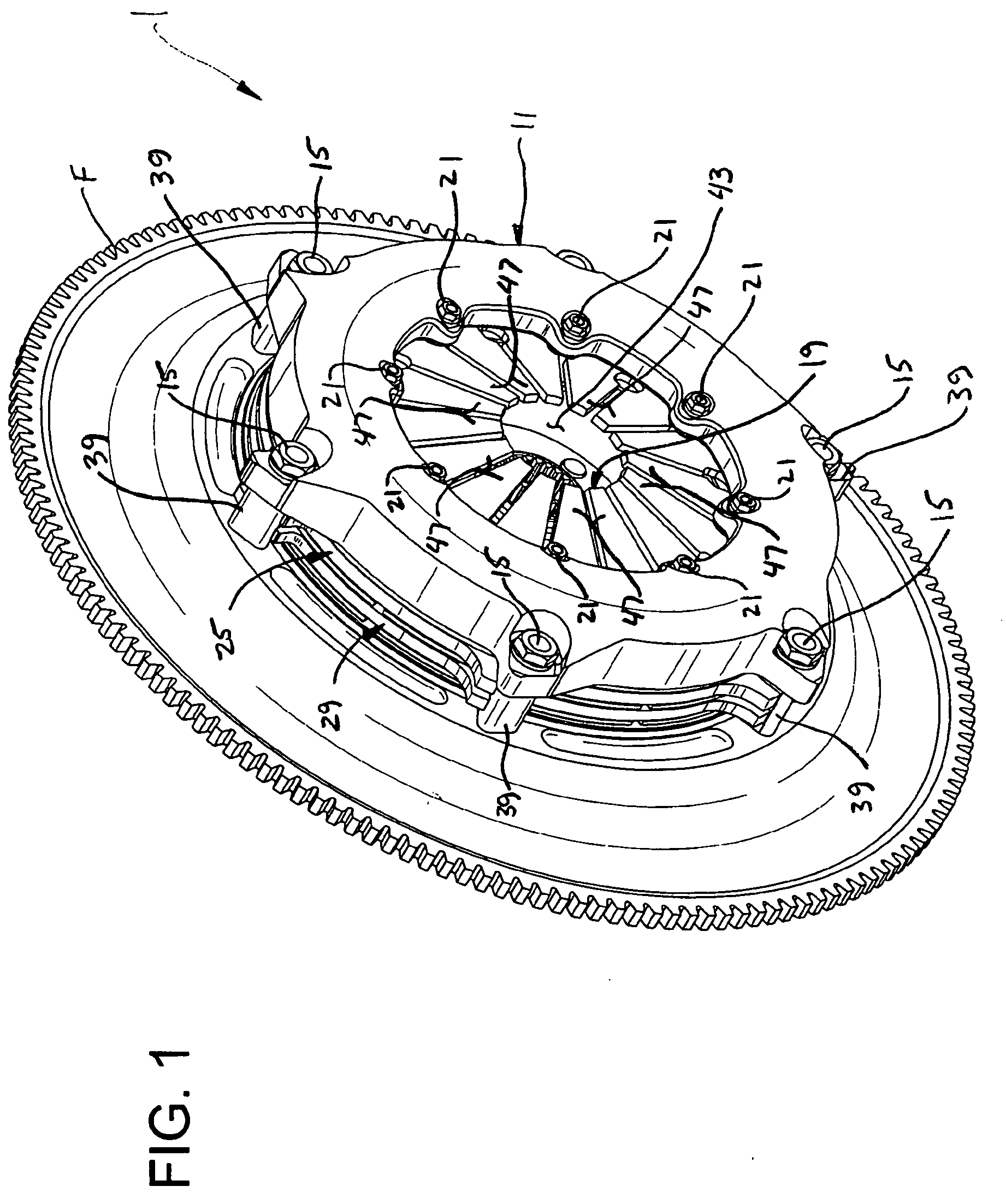
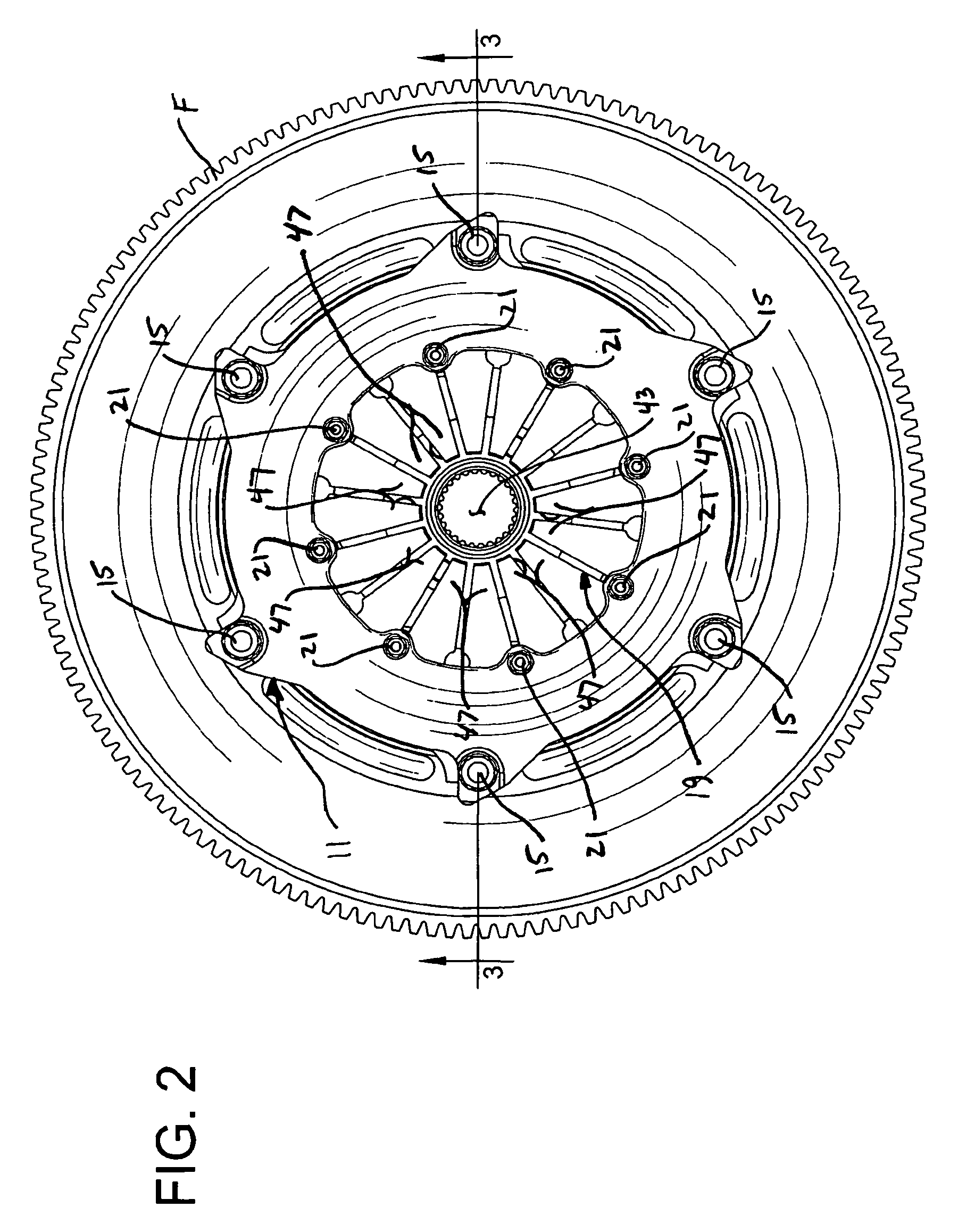
[0032] Referring now to the drawings, and first to FIGS. 1-3, a friction clutch assembly of the present invention is generally indicated at 1. The friction clutch assembly interconnects a powered, driving shaft A to a driven shaft B. Typically the driving shaft A is an engine crankshaft of an automotive vehicle which is attached to a flywheel F, and the driven shaft is a transmission gearbox input shaft. The driving shaft A and driven shaft B are axially aligned and can be operatively connected through the clutch 1 so that torque is transmitted and the shafts rotate together. A driver of the vehicle uses the clutch 1 to selectively disconnect the shafts A, B, interrupting the transmission of torque, in order to permit a gear shifting operation in the transmission.

[0033] As seen in FIGS. 3 and 4, the friction clutch assembly 1 includes a cover, generally indicated 11, attached to the flywheel F by conventional fasteners 15 for fixed rotational engagement with the driving shaft A. In...


PUM

PropertyMeasurementUnit
torqueaaaaaaaaaa
pressureaaaaaaaaaa
frictionaaaaaaaaaa

Abstract

A friction clutch assembly comprises a cover mounted on a flywheel of a driving shaft. A pressure plate has a contact surface for receiving a driving force from the driving shaft that is axially moveable between an engaged position and a disengaged position. A spring supported by the cover urges the pressure plate into the engaged position. Compression of the spring releases pressure on the pressure plate to permit movement of the pressure plate to the disengaged position. At least one spacer attached to the cover and flywheel has an external surface that engages the pressure plate upon rotation of the flywheel. The external surface of the spacer conforms to the contact surface of the pressure plate so that torque is transmitted between the flywheel and the pressure plate over at least a line of engagement of the spacer external surface and the pressure plate contact surface upon rotation of the flywheel. The cover may have a continuous curved surface with a varying radius of curvature over a length of the curve to resist deflection and prevent premature failure of the cover.

Description

CROSS-REFERENCE TO RELATED APPLICATION [0001] This application is a divisional of U.S. patent application Ser. No. 10 / 727,687, filed Dec. 4, 2003, the entire disclosure of which is incorporated herein by reference.BACKGROUND OF THE INVENTION [0002] The present invention relates generally to friction clutches, and in particular to a clutch assembly used in high performance vehicles such as racing cars. [0003] As is well known, vehicle clutches operate to selectively couple and decouple an engine to a drive shaft for the purpose of starting the engine while the vehicle is in gear, bringing the vehicle to a stop while the engine is running, changing gears while the vehicle is in motion and putting the vehicle in motion from a dead stop. Conventional clutches include a cover assembly having an annular cover plate and at least one annular pressure plate connected to the cover plate for conjoint rotation with the cover plate. The cover plate is fixedly attached to a flywheel driven by the...

Claims


Application Information

Patent Timeline
Patent Type & Authority Applications(United States)
IPC IPC(8): F16D13/52F16D13/58F16D13/71
CPCF16D13/585Y10T29/49721F16D13/71
Inventor FOX, JAMES
Owner ACE MFG & PARTS
Why Eureka
Try Eureka