

Clamp
a clamping and clamping technology, applied in the field of clamping, can solve the problems of slow and unsafe operation, complicated positioning of the end of the gun over the clamping, and difficult use of devices such as nail guns for fixing
- Summary
- Abstract
- Description
- Claims
- Application Information
AI Technical Summary
Benefits of technology
Problems solved by technology
Method used
Image

Examples
Embodiment Construction
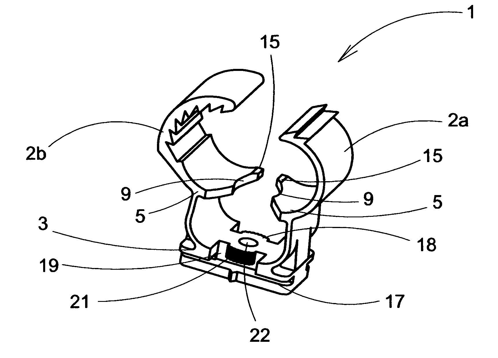
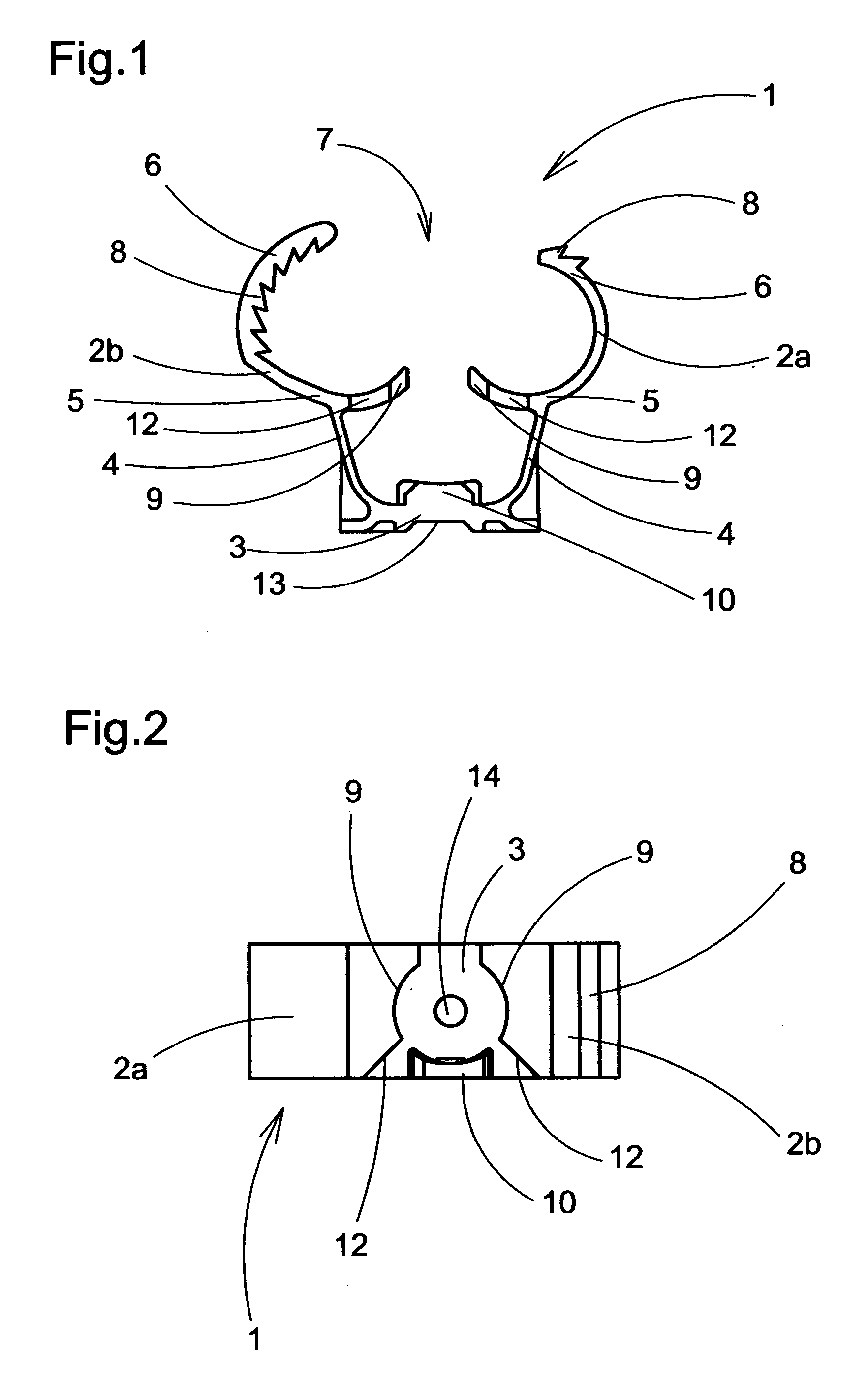
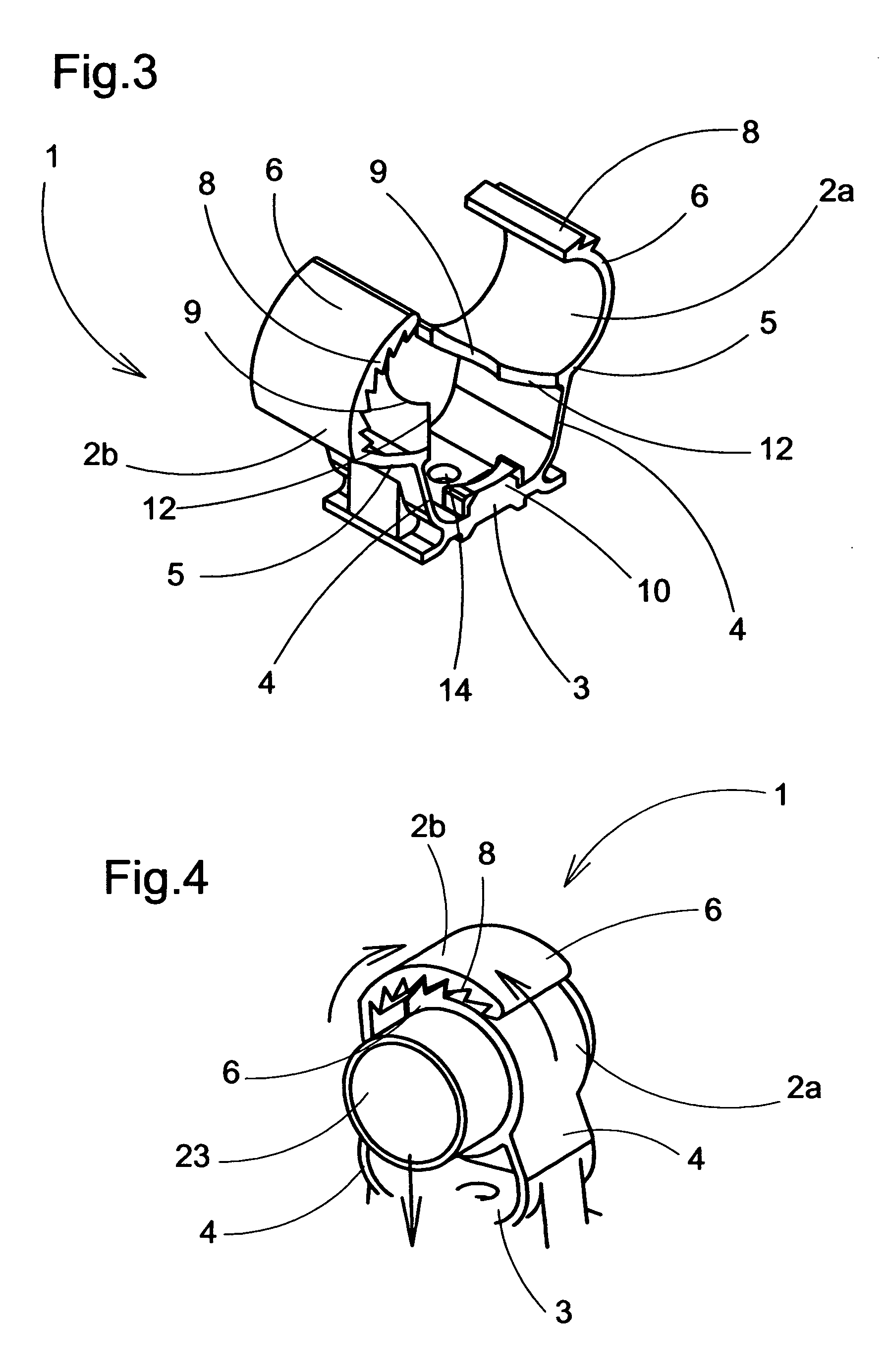
[0008] The aim of the clamp of the present invention is to solve the drawbacks of the devices known in the art, providing a clamp for pipes and the like, comprising two lateral arms for fixing the pipe between them and articulation means of each arm to a base for receiving a fixing element to a wall or the like propelled by a fixing device from an outlet mouth, each of said arms including a lower end closer to said base which closes the arms when pushing the pipe against it, and an upper end farther from said base which includes means for blocking both arms when they are closed, characterized in that it comprises, at the lower end of the arms, attaching means to the end of the outlet mouth of the fixing device.
[0009] Preferably, the attaching means to the fixing device comprise recesses at the lower end of the arms having a profile complementary to the contour of the mouth of the device, the base of the clamp being placed in front of the outlet orifice of the mouth of the device.
[...
PUM
 Abstract
Description
Claims
Application Information